Publication Date: 2021-01-26
Approval Date: 2020-12-11
Submission Date: 2020-11-20
Reference number of this document: OGC 20-087
Reference URL for this document: http://www.opengis.net/doc/PER/ISG-Sprint
Category: OGC Public Engineering Report
Editors: Leonard Daly, Scott Serich
Title: Interoperable Simulation and Gaming Sprint Engineering Report
COPYRIGHT
Copyright ©2021, Open Geospatial Consortium. To obtain additional rights of use, visit http://www.opengeospatial.org/
WARNING
This document is not an OGC Standard. This document is an OGC Public Engineering Report created as a deliverable in an OGC Interoperability Initiative and is not an official position of the OGC membership. It is distributed for review and comment. It is subject to change without notice and may not be referred to as an OGC Standard. Further, any OGC Public Engineering Report should not be referenced as required or mandatory technology in procurements. However, the discussions in this document could very well lead to the definition of an OGC Standard.
LICENSE AGREEMENT
Permission is hereby granted by the Open Geospatial Consortium, ("Licensor"), free of charge and subject to the terms set forth below, to any person obtaining a copy of this Intellectual Property and any associated documentation, to deal in the Intellectual Property without restriction (except as set forth below), including without limitation the rights to implement, use, copy, modify, merge, publish, distribute, and/or sublicense copies of the Intellectual Property, and to permit persons to whom the Intellectual Property is furnished to do so, provided that all copyright notices on the intellectual property are retained intact and that each person to whom the Intellectual Property is furnished agrees to the terms of this Agreement.
If you modify the Intellectual Property, all copies of the modified Intellectual Property must include, in addition to the above copyright notice, a notice that the Intellectual Property includes modifications that have not been approved or adopted by LICENSOR.
THIS LICENSE IS A COPYRIGHT LICENSE ONLY, AND DOES NOT CONVEY ANY RIGHTS UNDER ANY PATENTS THAT MAY BE IN FORCE ANYWHERE IN THE WORLD. THE INTELLECTUAL PROPERTY IS PROVIDED "AS IS", WITHOUT WARRANTY OF ANY KIND, EXPRESS OR IMPLIED, INCLUDING BUT NOT LIMITED TO THE WARRANTIES OF MERCHANTABILITY, FITNESS FOR A PARTICULAR PURPOSE, AND NONINFRINGEMENT OF THIRD PARTY RIGHTS. THE COPYRIGHT HOLDER OR HOLDERS INCLUDED IN THIS NOTICE DO NOT WARRANT THAT THE FUNCTIONS CONTAINED IN THE INTELLECTUAL PROPERTY WILL MEET YOUR REQUIREMENTS OR THAT THE OPERATION OF THE INTELLECTUAL PROPERTY WILL BE UNINTERRUPTED OR ERROR FREE. ANY USE OF THE INTELLECTUAL PROPERTY SHALL BE MADE ENTIRELY AT THE USER’S OWN RISK. IN NO EVENT SHALL THE COPYRIGHT HOLDER OR ANY CONTRIBUTOR OF INTELLECTUAL PROPERTY RIGHTS TO THE INTELLECTUAL PROPERTY BE LIABLE FOR ANY CLAIM, OR ANY DIRECT, SPECIAL, INDIRECT OR CONSEQUENTIAL DAMAGES, OR ANY DAMAGES WHATSOEVER RESULTING FROM ANY ALLEGED INFRINGEMENT OR ANY LOSS OF USE, DATA OR PROFITS, WHETHER IN AN ACTION OF CONTRACT, NEGLIGENCE OR UNDER ANY OTHER LEGAL THEORY, ARISING OUT OF OR IN CONNECTION WITH THE IMPLEMENTATION, USE, COMMERCIALIZATION OR PERFORMANCE OF THIS INTELLECTUAL PROPERTY.
This license is effective until terminated. You may terminate it at any time by destroying the Intellectual Property together with all copies in any form. The license will also terminate if you fail to comply with any term or condition of this Agreement. Except as provided in the following sentence, no such termination of this license shall require the termination of any third party end-user sublicense to the Intellectual Property which is in force as of the date of notice of such termination. In addition, should the Intellectual Property, or the operation of the Intellectual Property, infringe, or in LICENSOR’s sole opinion be likely to infringe, any patent, copyright, trademark or other right of a third party, you agree that LICENSOR, in its sole discretion, may terminate this license without any compensation or liability to you, your licensees or any other party. You agree upon termination of any kind to destroy or cause to be destroyed the Intellectual Property together with all copies in any form, whether held by you or by any third party.
Except as contained in this notice, the name of LICENSOR or of any other holder of a copyright in all or part of the Intellectual Property shall not be used in advertising or otherwise to promote the sale, use or other dealings in this Intellectual Property without prior written authorization of LICENSOR or such copyright holder. LICENSOR is and shall at all times be the sole entity that may authorize you or any third party to use certification marks, trademarks or other special designations to indicate compliance with any LICENSOR standards or specifications.
This Agreement is governed by the laws of the Commonwealth of Massachusetts. The application to this Agreement of the United Nations Convention on Contracts for the International Sale of Goods is hereby expressly excluded. In the event any provision of this Agreement shall be deemed unenforceable, void or invalid, such provision shall be modified so as to make it valid and enforceable, and as so modified the entire Agreement shall remain in full force and effect. No decision, action or inaction by LICENSOR shall be construed to be a waiver of any rights or remedies available to it.
None of the Intellectual Property or underlying information or technology may be downloaded or otherwise exported or reexported in violation of U.S. export laws and regulations. In addition, you are responsible for complying with any local laws in your jurisdiction which may impact your right to import, export or use the Intellectual Property, and you represent that you have complied with any regulations or registration procedures required by applicable law to make this license enforceable.
- 1. Subject
- 2. Executive Summary
- 3. References
- 4. Terms and definitions
- 5. Overview
- 6. Material and Purpose
- 7. Findings
- 8. Conclusions
- 9. Component Implementation: CAE
- 10. Component Implementation: Cesium
- 11. Component Implementation: Cognitics
- 12. Component Implementation: Ecere
- 12.1. Overview
- 12.2. Server Implementation
- 12.2.1. Improvements to CDB preprocessing
- 12.2.2. Improvements to 3D Tiles generation
- 12.2.3. OGC API - Common end-points
- 12.2.4. 3D Tiles Bounding Volume Hierarchy end-points
- 12.2.5. OGC API - Tiles and 3D Models extension end-points
- 12.2.6. Other OGC API end-points
- 12.2.7. Technology Integration Experiments
- 12.3. Updating the 3D content
- 12.4. Client Implementation
- 12.5. GeoVolumes API Considerations
- 13. Component Implementation: Helyx
- 13.1. Types of alternate distribution in scope of GeoVolumes API
- 13.2. What is an alternate distribution?
- 13.3. Representing Alternate Distributions at the Data Level
- 13.4. Representing Alternate Distributions at the Service Level
- 13.5. Representing Alternate Distributions at the API Level
- 13.6. What Datasets, Services or Tiling Schemes are ‘In Scope’ of the GeoVolumes API?
- 13.7. Representing Alternate Distributions at the Collection(s) Level.
- 13.8. Representing Alternate Distributions within one API – endpoints
- 13.9. Representing Alternate Distributions within one API – parameters
- 13.10. A note on path format
- 13.11. Representing Alternate Distributions within one API - Link Relations
- 13.12. Representing Alternate Distributions as Media Types
- 13.13. What is the difference between an alternate distribution and an alternate resource?
- 13.14. Practical use of alternate distributions at the client side
- 13.15. OpenAPI Shapechange Workflow Perspective
- 13.16. Benefits
- 14. Component Implementation: Hexagon GSP
- 15. Component Implementation: InfoDao
- 16. Component Implementation: SimBlocks.io
- 17. Component Implementation: Steinbeis
- 18. Future Recommendations
- Appendix A: Technology Integration Experiment (TIE) Table
- Appendix B: Revision History
- Appendix C: Bibliography
1. Subject
The OGC Interoperable Simulation and Gaming Sprint advanced the use of relevant OGC and Khronos standards in the modeling and simulation community through practical exercise and testing of the GeoVolumes API draft specification produced by the 3D Data Container and Tiles API Pilot. Of particular interest was the handling and integration of glTF models coming from multiple sources, but the sprint also examined the specification’s implementability, consistency, completeness, and maturity.
2. Executive Summary
The Interactive Simulation and Gaming Sprint ("Sprint") was undertaken by OGC to verify the results of the 3D Data Container and Tiles API Pilot ("Pilot"). The Pilot produced the OGC GeoVolumes API draft specification ("draft spec" [1]). The Sprint was specifically designed to test the coverage and consistency of the draft spec and with respect to other OGC APIs. It was expected that the Sprint would uncover no major issues with the draft spec, but would identify interoperability issues with multiple data stores and between other OGC APIs. The Sprint was not intended as a full-coverage verification and validation of the draft spec.
As indicated in the OGC 3D Data Container and Tiles API Pilot Summary Engineering Report [2], it was important from a business perspective that additional integration tests and real-world deployment demonstrations further explore the potential of the GeoVolumes API draft spec. The implementation and testing work conducted in this initiative went a long way toward resolving any outstanding interoperability issues and exploring best practices for the organization of GeoVolumes within the interoperable simulation and gaming domain.
Another important component in the Sprint was the use of 3D models in (graphics language transmission format (glTF) [3]). This format is of particular interest to OGC because of its emergence as a common (i.e., de facto standard) web transmission model format. The format was developed and is supported by the Khronos Group, which was a partner in the Sprint.
Please also visit the OGC ISG Sprint YouTube Playlist to view participant video recordings.
2.1. Operation
The Sprint implementation work lasted six weeks, primarily during September 2020. The original plan called for a week-long in-person coding effort; however, due to the Covid-19 pandemic, this was changed to a virtual event with each participant providing their own development support.
The primary source data used in the Sprint was from the San Diego CDB dataset, which implemented the OGC CDB Standard [4]. Other data formats such as OpenFlight [5] were also used.

The participants for the Sprint were (in alphabetical order): CAE, Cesium, Cognitics, Ecere, Helyx, Hexagon, InfoDao, SimBlocks, and Steinbeis. Most participants had experience participating in prior OGC projects. All participants were OGC member organizations.
The Sprint Call for Participation (CfP) [6] provided three scenarios. Participants could also propose their own scenario provided that fit within Sprint guidelines. Table 2 provides a summary description of the selected scenarios. Table 3 shows the coverage of scenarios by the participants.
2.2. Accomplishments
All of the participants worked together using each other’s resources and expertise to augment their work. The Technology Integration Experiment (TIE) Table shows the full results of their cooperative work testing their GeoVolumes API implementations and those of others.
Through the development and testing work undertaken in the Sprint, the participants tested a wide range of GeoVolumes API draft spec coverage. No serious defects were discovered, and no major problems with correctness, completeness, or consistency were reported. Significant results that were reported include:
-
Use of a previously unused dataset (San Diego CDB) with the draft spec,
-
Hosting a GeoVolumes API service on Amazon Web Services without issue,
-
Partial integration with OGC’s SensorThings API,
-
Dynamic update of models in the datastore,
-
Dynamic update of terrain used in the datastore, and
-
Partial integration with Unity’s game engine.
2.3. Issues
As expected, the Sprint did identify several issues. Most of these were not with the GeoVolumes API draft spec but with the underlying support. One item that all participants noted (and no solution was provided) was the lack of an optimized conversion between the various data formats that were used. This included CDB, glTF, and OpenFlight.
The participants did investigate issues arising from differences between various OGC APIs. The primary finding was that the OGC API - Common - Part 2: Geospatial Data was a key document. Issues would have arisen if the various functional specifications were inconsistent with this specification. At the time of the investigation, no inconsistencies had been discovered.
Most of the issues with the GeoVolumes API draft spec were in the areas of definitions and use of URLs and HTTP requests and replies. These issues did not prevent the APIs from working, but differences could arise between different implementations in areas where the draft spec does not go into that level of detail.
Three items were identified as involving URLs. Mostly it was a case of determining how the URL path end-point (final component of the path) was used to access specific data format. This is tied in with the issue noted in Media Type. A minor note is that the GeoVolumes draft specification is not completely clear on the server environment. An issue might arise if the server (the part of the system that provides the data through the API) is configured as a file server (responds to the file protocol).
Issues involving HTTP concerned the use of Request Methods, Media Type, and Request Attributes. These issues did not prevent the API from working, but could cause some interoperability issues in larger-scale environments.
Issues with Request Methods addressed how a data change should be made to the datastore. Media types allow the client and server to communicate as to the format of the data. This interacted with the URL issues (described above) by controlling how a specific format of data is requested and received. Request attributes assist in the means to specify alternate or roll-over data sources.
2.4. Recommendations
Seventeen recommendations were made for future work. These items are generally referred to as "projects," but they could be fairly brief and small undertakings by a Domain or Standards Working Group or as part of another effort (Sprint, Pilot, Testbed, etc.) within OGC. Items not directly part of OGC could also be addressed through appropriate joint projects or liaison arrangements with external organizations/groups.
These range from projects external to OGC (four projects) generally carried out by other organizations or community efforts, three data based projects (generally conversion from one format to another), three projects to enhance the GeoVolumes API draft spec, four projects to develop a clear definition of feature (model or terrain) change (part to HTTP Request Method discussed above), and three on API infrastructure (to address the URL and HTTP issues described above).
2.5. Document contributor contact points
All questions regarding this document should be directed to the editor or the contributors:
Contacts
| Name | Organization | Role |
|---|---|---|
Leonard Daly |
Daly Realism representing Khronos Group |
Contributor & Editor |
Scott Serich |
Open Geospatial Consortium |
Contributor & Editor |
Holly Black |
CAE |
Contributor |
Sean Lilley |
Cesium |
Contributor |
Michala Hill |
Cognitics |
Contributor |
Jerome St-Louis |
Ecere |
Contributor |
Anneley Hadland |
Helyx |
Contributor |
Emeric Beaufays |
Hexagon |
Contributor |
Joshua Rentrope |
InfoDao |
Contributor |
Jordan Dauble |
SimBlocks.io |
Contributor |
Patrick Caughey |
SimBlocks.io |
Contributor |
Barbara Cotter |
SimBlocks.io |
Contributor |
Glenn Johnson |
SimBlocks.io |
Contributor |
Joseph Kaile |
SimBlocks.io |
Contributor |
Volker Coors |
Steinbeis, HFT Stuttgart |
Contributor |
Thunyathep Santhanavanich (Joe) |
Steinbeis, HFT Stuttgart |
Contributor |
Harpreet Singh |
Steinbeis, HFT Stuttgart |
Contributor |
Patrick Würstle |
Steinbeis, HFT Stuttgart |
Contributor |
2.6. Foreword
Attention is drawn to the possibility that some of the elements of this document may be the subject of patent rights. The Open Geospatial Consortium shall not be held responsible for identifying any or all such patent rights.
Recipients of this document are requested to submit, with their comments, notification of any relevant patent claims or other intellectual property rights of which they may be aware that might be infringed by any implementation of the standard set forth in this document, and to provide supporting documentation.
3. References
The following normative documents are referenced in this document:
-
3D Tiles Specification 1.0. (c) 2016-2019, Cesium and Open Geospatial Consortium,
-
glTF V2.0 Specification, 9 June 2017. (c) 2017, The Khronos Group,
-
GeoVolumes Draft Specification. (c)2020, Open Geospatial Consortium,
-
Uniform Resource Identifier (URI): Generic Syntax. RFC 3986, IETF., and
-
SensorThings API Specification. (c)2015,2017; Open Geospatial Consortium.
4. Terms and definitions
For the purposes of this report, the definitions specified in Clause 4 of the OWS Common Implementation Standard OGC 06-121r9 shall apply. In addition, the following terms and definitions apply.
- ● 3D Tiles
-
3D Tiles [7] is designed for streaming and rendering massive 3D geospatial content such as Photogrammetry, 3D Buildings, BIM/CAD, Instanced Features, and Point Clouds. It defines a hierarchical data structure and a set of tile formats which deliver renderable content. 3D Tiles does not define explicit rules for visualization of the content; a client may visualize 3D Tiles data however it sees fit.
- ● b3dm
-
Batched 3D Model (b3dm) [8] allows offline batching of heterogeneous 3D models, such as different buildings in a city, for efficient streaming to a web client for rendering and interaction. Efficiency comes from transferring multiple models in a single request and rendering them in the least number of WebGL draw calls necessary. Using the core 3D Tiles spec language, each model is a feature.
- ● CDB
-
The CDB standard [4] defines a standardized model and structure for a single, “versionable,” virtual representation of the earth. A CDB structured data store provides for a geospatial content and model definition repository that is plug-and-play interoperable between database authoring workstations. Moreover, a CDB structured data store can be used as a common online (or runtime) repository from which various simulator client-devices can simultaneously retrieve and modify, in real-time, relevant information to perform their respective runtime simulation tasks. In this case, a CDB is plug-and-play interoperable between CDB-compliant simulators. A CDB can be readily used by existing simulation client-devices (legacy Image Generators, Radar simulator, Computer Generated Forces, etc.) through a data publishing process that is performed on-demand in real-time.
- ● Full Motion Video (FMV)
-
Full Motion Video (FMV)-compliant refers to the combination of a video stream and associated metadata into one video file, which makes the video geospatially aware. The sensor systems collect camera pointing information, platform position and attitude, and other data, and encode it into the video stream so that each video frame is associated with geopositional information [9].
- ● GeoVolumes
-
GeoVolumes [10] follow one conceptual organization of space applied by humans, which is a nested collection of spaces where every space contains either a number of sub-spaces or a set of objects. As an example, the GeoVolume “Earth” contains a set of child GeoVolumes, one for each continent. Each continent then may have a set of child GeoVolumes for the various countries, or, if countries are irrelevant in that scenario, a number of datasets that represent the topography, rivers, and human settlements.
- ● IANA
-
Internet Assigned Numbers Authority is the organization responsible for oversight of the architecture of the Internet. They are ultimately responsible for assignment of IP addresses and management of Media Types.
- ● jp2 | JPEG2000
-
It is an advanced lossy compression algorithm for representing 2D data. It is currently not widely supported in browsers, requiring a (CPU-intensive) conversion to JPEG or PNG/GIF.
- ● OpenFlight
-
OpenFlight [5] is a file format originally designed as a nonproprietary 3D geometry model format for use by real-time 3D visual simulation image generators. The OpenFlight file format is used today in the high end real-time visual simulation industry as the standard interchange format between different IG systems, and is currently administrated by Presagis [11].
- ● URL/URI
-
At one time Uniform Resource Location (URL) was a subset of Uniform Resource Identifier (URI). Now both are considered the same [12].
- ● W3C
-
World Wide Web Consortium is responsible for all standards that make the Web operate, including URIs, HTTP, etc.
5. Overview
Section 6 describes the Material and Purpose of the Sprint. All of the material that was provided to the participants is either included here or referenced.
Section 7 presents the overall Findings from the Sprint. The discussion includes material learned from all participants and the Sprint leadership team in carrying out the Sprint.
Section 8 presents the major Conclusions from the Sprint. This represents the collective knowledge and experience of the participants and editor.
Sections 9-17 contain the Participant Detailed Reports.
Section 18 contains the consolidated Future Recommendations. Much of this content was gathered from participant detailed reports.
Appendix A contains a copy of the Sprint Technology Integration Experiments (TIE) Table, with additional notes and comments.
Appendix B contains the document Revision History.
Appendix C contains the document Bibliography.
6. Material and Purpose
6.1. Call for Participation
The ISG Sprint: Call for Participation (CfP) [6] was released on 7 July 2020 by the Open Geospatial Consortium for the purpose of obtaining proposals from organizations interested in furthering study of the GeoVolumes draft specification [1]. The CfP provided all of the material necessary for organizations to make a proposal for participation either by direct inclusion in the document or publicly available links.
The CfP specified a schedule from kickoff meeting (1 September) through the Sprint Week (21-25 September), and participant final report inputs (5 October). The Sprint was originally desired to be in-person; however, pandemic lockdown restrictions required that all participant work be done remotely during the sprint week. This decision was made prior to the due date for proposals.
6.2. Data Sets
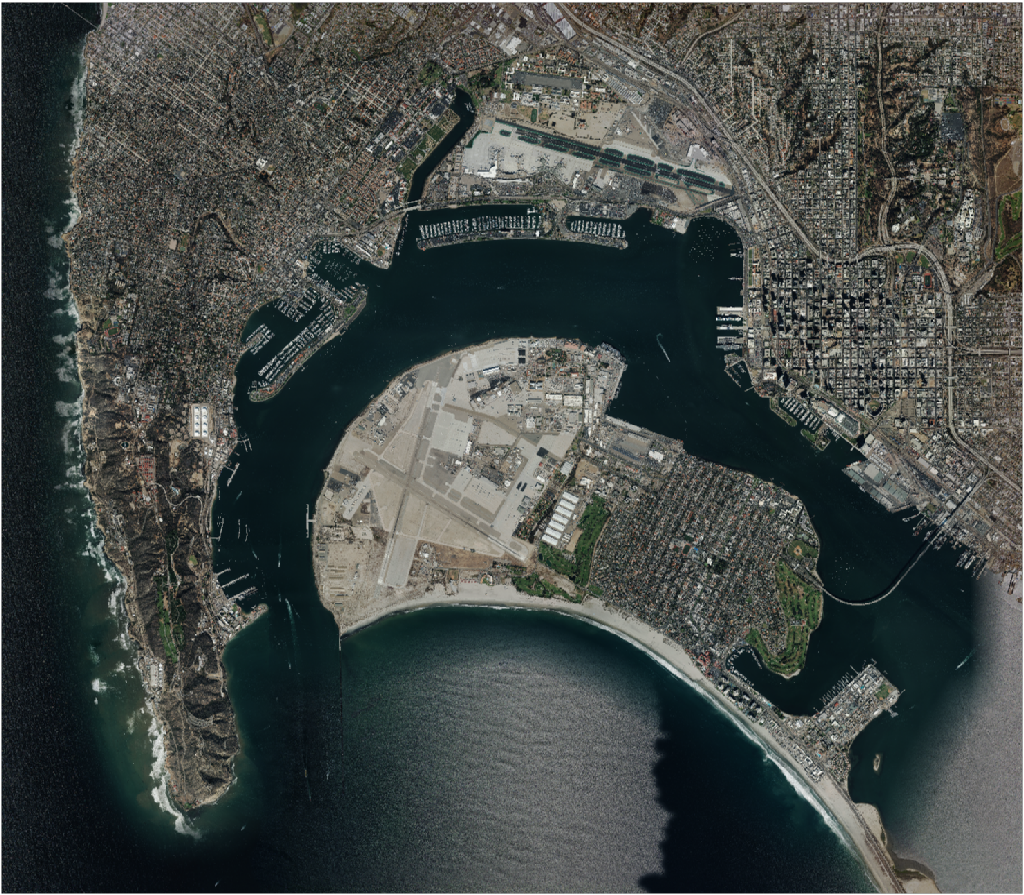
The primary data set for the Sprint is known as San Diego CDB (licensed under the SanGIS Legal Notice - SanGIS GIS Data End User Use Agreement and Disclaimer for Data Released to the Public [13]). This data set was collected using a number of sensors and methods from <start> to <end> and encompassed nearly all of the downtown San Diego and vicinity, including the port, sports stadium, recreational facilities, commercial, and housing areas.


All participants could elect to use other datasets, particularly any of those from the OGC 3D Data Container and Tiles API Pilot (aka "Pilot") [2]. In particular, much use was made of the New York data set.

The San Diego CDB was available for download by all participants. Many of the participants made that data available to all participants through the GeoVolumes API on their servers. New York data was also made available through multiple APIs implemented during the Pilot. See Table 1 for a list of available servers.
6.3. 3D GeoVolume Servers
Several of the Sprint participants also participated in the Pilot. These organizations provided their GeoVolumes API servers for use to everyone during the Sprint. These servers were generally populated with both the New York and San Diego data.
| Organization | URL | Notes |
|---|---|---|
Cesium |
Server |
|
Cesium |
Client |
|
Cognitics |
n/a |
|
Ecere |
/collections/SanDiegoCDB in particular, with Tiles API and GeoVolumes/3D Tiles |
|
New York City 3D Tiles dataset (static server) |
||
Helyx |
n/a |
|
InfoDao |
PyGeoAPI serving San Diego and Copenhagen CDB (base url has rest of API) |
|
Skymantics |
n/a |
|
Steinbeis |
New Steinbeis 3D GeoVolumes server for OGC-ISG |
|
Existing Steinbeis 3D GeoVolumes server from the 3D Container and Tiles pilot, containing New York City 3D Tiles dataset, New York City I3S dataset |
||
STT 3D Client (based on CesiumJS & ArcGIS for JavaScript) |
||
STT 3D Client (by Fraunhofer and GeoRocket) |
6.4. GeoVolumes API Pilot Engineering Report
The three 3D Data Container and Tiles API Pilot engineering reports (collectively referred to as "Pilot ER") [14, 1, 2] were made available to all participants prior to kickoff. Subsequent to the start of the Sprint, the Pilot ER was made publicly available. The draft specification is part 2 [1] of the document set. This contained the API specification that was the primary target of the Sprint.
6.5. Architecture diagrams
These architecture diagrams were provided with the CfP. Figure 5 illustrates the service architecture of the 3D Data Container and Tiles environment that includes the GeoVolumes API. Figure 6 illustrates access to city-based datasets (in particular for New York, US and Montreal, CA), but only showing the detail for New York City.

Arrows show the potential paths of requests from the clients; data flow is in the reverse direction. The connecting lines indicate conceptual requests and data flows. The actual connections may be distributed across several physical devices.

This figure is presented as an illustration of possible connections. It is not intended to be a complete illustration of all connections or possible data sets.
6.6. Discussion of Scenarios
The CfP described three possible scenarios [6]. Participants could choose to work on any number of these, any variant of these, or one (or more) of their choosing.
-
Investigate how model and terrain updates, originating (preferred) from a CDB data store and delivered as glTF, are integrated with 3D Tiles into the client environment. The questions to be examined should include the following.
-
How are terrain changes handled with existing structures?
-
How are new models integrated with existing elevation terrain?
-
How are existing models handled when CDB updates indicate change (additions/deletions/configurations)?
-
-
Containers may specify 0 or 1 datasets. A dataset indicates a primary and potentially one or more alternate distributions. Investigate whether there are implementation issues with accessing multiple distributions.
-
What should be the organization of the underlying 3D data? It is unlikely that there is a single best solution to these problems, so identifying use cases for particular choices will be important.
-
Is there one bounding volume hierarchy per county, region, city, or some other geo-political boundaries?
-
How are features (buildings, vegetation, transportation networks, etc.) structured in the data store? Are they layers in geo-political sets, or are geo-political data layers in feature sets?
-
These scenarios were designed to test and explore portions of the draft GeoVolumes specification that OGC and the sponsors felt were not sufficiently explored in the Pilot. They derive directly from the discussion from Chapter 10 of the Extended Executive Summary [2]. In addition to the listed scenarios, participants were invited to explore other areas that fit within the opportunities described in Chapter 10. Some of the participants did use this option to explore other capabilities, especially related to game-engine integration. The Findings chapter of this report discusses the participant’s scenario choices.
7. Findings
7.1. Introduction
This section describes findings of the Sprint participants. Each finding presented here is significant in that is was reported by at least two participants or it was a serious issue reported by a single participant.
Not all participants investigated the same aspects of the draft Specification. This approach enabled fairly expansive testing of the draft Specification and related areas.
7.2. Aspects of Investigation
Each participant was free to choose which one (or more) scenarios to pursue. Three scenarios were discussed in the CfP [6]. Participants could also create their own scenario. OGC reviewed each participant’s proposal and suggested revisions to better align with the goals of the Sprint, the interest of the Sponsor, and the coverage by the other participants. Table 2 provides a summary description of the selected scenarios. Table 3 shows the coverage of scenarios by the participants.
| Scenario | Summary Desription |
|---|---|
1 |
Investigate model and terrain updates |
2 |
Investigate alternate and multiple distributions |
3 |
Investigate organization of underlying 3D data |
Other-1 |
Investigate integration with Rapid3D (Full Motion Video) |
Other-2 |
Investigate the integration of GeoVolumes API with Unity game engine |
| Participant | Scenario 1 | Scenario 2 | Scenario 3 | Other |
|---|---|---|---|---|
✓ |
||||
✓ |
||||
✓ |
1 |
|||
✓ |
||||
✓ |
||||
✓ |
||||
✓ |
✓ |
|||
2 |
||||
✓ |
✓ |
7.3. Cooperative Efforts
All participants cooperated with each other in various aspects of the Sprint. This included a team entry, providing data services for the Sprint, and use and testing of other OGC API services.
Two teams were formed. Three participants, CAE, Cesium, and Cognitics, teamed together to produce a combined result. This was done with the knowledge and approval of the sponsor. A two participant team (Ecere and Steinbeis) was formed to test the insertion, modification, and deletion of 3D objects and terrain into the base scene.
All participants cooperated and included the test and use of other participant services during the Sprint. Use and testing was performed by all members agains OGC GeoVolumes API services offered by others. Table 4 shows the interoperation between offered services (servers) and uses (clients).
| Client → | Hexagon | InfoDao | SimBlocks | Steinbeis |
|---|---|---|---|---|
Service |
||||
Cesium |
✓ (+ fdbk) |
✓ [pilot] |
✓ [pilot] |
✓ [pilot] |
Cognitics |
✓ [pilot] |
NA |
✓ [pilot] |
✓ [pilot] |
Ecere |
✓ [San Diego] |
✓ [San Diego] |
✓ [San Diego] |
✓ [San Diego] |
(Pilot functions) Ecere |
✓ [pilot] |
✓ [pilot] |
✓ [pilot] |
✓ [pilot] |
PyGeoAPI-InfoDao |
✓ |
using CDB server |
NA |
not pass |
Helyx |
✓ [pilot, San Diego] |
✓ [pilot, San Diego] |
✓ [pilot, San Diego] |
✓ [pilot, San Diego] |
Steinbeis New |
✓(+ fdbk) |
✓ [San Diego] |
✓ [San Diego] |
✓ [San Diego] |
(Pilot functions) Steinbeis Existing |
✓ [pilot] |
✓ [pilot] |
✓ [pilot] |
✓ [pilot] |
7.4. General Results
The work done for the Sprint was closely tied to the work done for the Pilot, even though some of the participants were different between the two initiatives. The mix of participants allowed some with extensive experience in GeoVolumes to dig deeper into areas that were not fully explored during the Pilot. Participants who were not part of the Pilot brought a fresh read to the document along with potential solutions.
No defects in the draft specification were discovered, though several items need further investigation. These are discussed in the Discovered Inconsistencies section. Several participants discussed the importance of GeoVolumes following the OGC API Core, Volume 2: 3D Data specification to ensure compatibility throughout the suite of OGC APIs.
In addition to the results shown in Table 4 the participants were able to use their existing GeoVolume client software to access data-stores that had not been previously used by OGC and OGC projects. These data-stores included data in CDB and other formats that either were served directly (as 3D Tiles static files) or generated on-the-fly from CDB and other sources.
Steinbeis extended one of the scenarios to include the integration of SensorThings API [15] to illustrate how these two APIs could work together (SensorThings API Server for Urban Mobility). There were no inconsistencies or other issues found.
It is worth mentioning that two participants (CAE and Cognitics) have hosted their services on Amazon Web Services (AWS) to improve throughput and allow for easy load expansion when needed. The use of cloud services was smooth and without issues. These were not tested for heavy loads, load balancing capabilities, or performance.
7.5. Dynamic Dataset Updates
Several of the participants developed the capability to update part of the dataset during operation. These updates do not require regeneration of the entire dataset from the data-store. There are mechanisms to ensure that any generated and cached files are appropriately rebuilt on the next request.
Ecere, Steinbeis, and Hexagon addressed the insert/update/removal models using the OGC API - Features standard. The specified API proved sufficient (but not necessarily ideal) to perform these functions within the context of GeoVolumes API and the Sprint. Ecere proposed an extension that provided a better interface to refer to models. All of these participants did note that getting the models to align with the local terrain was not a simple matter and required different solutions depending on how the client was designed and configured.
7.6. Performance Comments
Nearly all of the participants noted that conversion of CDB to 3D Tiles was an expensive operation and needed to be avoided especially for on-the-fly requests. Cesium noted that in addition to the performance issues associated with conversion, the high-detailed building files are (generally) very large (50-100MB), and improving the tiling scheme is needed to maintain performance of the server and client.
Another issue noted by Ecere and Cesium (among others) was handling the creation of glTF files. In particular the manipulation of meshes. Some of the supporting libraries may require a particular condition (e.g., each mesh only uses a single material) while the output may require a single mesh with multiple materials.
7.7. Discovered Inconsistencies
Several of the participants discovered various issues related to HTTP transactions. These include issues in the URL, request method, content-type, and, request attributes. The issues and possible solutions are interrelated. Each issue is linked to the section of the participants report where it is discussed in detail.
7.7.1. URLs
Issues with the URL were noted by several participants. These include
-
Different servers using GeoVolumes API use different relative URLs for models. In some cases it is a full path, other cases it is relative to the current document. It is consistent within a sever. SimBlocks discusses this in Server Testing.
-
The end-point requirements for are not always sufficiently clear. Helyx observed (Representing Alternate Distributions at the Collection(s) Level) that there is a lack of clarity in how to specify the alternate distributions. It may be specified as the final element in a path (endpoint), via search parameters, or through content-type negotiation.
-
Conflicts between OGC specifications and operating system requirements for use of the characters
/(slash) and:(colon). See the Helyx A note on Path Format.
|
Note
|
"Uniform Resource Identifier (URI): Generic Syntax" [16] specifies that the colon (":") is a reserved character and needs to be URL-encoded. This requirement may be sufficient for URI access, but if the system needs to support static file-mode access; there may be issues with Windows-based servers. |
7.7.2. Request Methods
Ecere, Steinbeis, and Hexagon investigated providing model and terrain change services. These include adding a new model, changing and existing model or terrain, deleting an existing model, replacing an existing model. From the discussion in the participant reports, there was no standard for executing those operations. The HTTP standard defines the methods GET (retrieve), POST (add new), PUT (replace existing), PATCH (update), and DELETE (delete) request methods that can be used for these operations. Ecere discusses the operation in detail in Updating the 3D content.
7.7.3. Media Type
The HTTP specification allows the client to specify the allowed media types that the server is allowed to return. The server may return a "Not Found" or other responses if the requested media type for that content is not available. If the various 3D data types have unique media types, the client may request a specific one through this mechanism. Helyx discussed some of these options in Representing Alternate Distributions as Media Types.
|
Note
|
Media types do not have to be approved by Internet Assigned Numbers Authority (IANA). There are provision for experimental and vendor-specific content types. It is generally easier to get IANA approval after a specification is approved by standards organization. |
7.7.4. Request Attributes
HTTP allows for an alternate or roll-over reference. This allows for the client code to indicate alternate distributions of the content-equivalent data. For example the primary reference may be 3D Tiles with a roll-over of i3s and CDB. Helyx discussed some of the issues and options in Representing Alternate Distributions within one API - Link Relations.
7.7.5. Other Friction Points
InfoDao noted that (GeoVolumes API Discussion: CDB comparisons and OGC API discussion) CDB and GeoVolumes APIs exist separately, but need to work together. The existing specifications (draft and approved) allow that to happen. There are issues with knowledge of the data structures are not necessarily known or easily handled on both the client and server sides of the communication link.
7.8. Game Engine Interface
SimBlocks.io worked on integrating their solution into the Unity game engine. There was quite a bit of work to do bringing in the 3D data as glTF or 3D Tiles into Unity. The solution they developed during the Sprint is sub-optimal, but it did work. They reported that they felt the solution for the Unreal engine would likely require a similar amount of work.
8. Conclusions
The basics of the GeoVolumes draft specification are complete and well-specified (consistent and complete). There may still be some edge cases that are poorly defined there were not investigated in the Sprint. A number of the participants indicated the importance of GeoVolumes and other OGC APIs to retain full consistency and compatibility with OGC API - Common, especially Draft OGC API - Common - Part 2: Geospatial Data.
Several participants noted issues with URLs and other HTTP issues. In a review of the statements by the participants and OGC API documents, it appears that various HTTP capabilities are not fully, correctly, or completely specified. This is highlighted in the Discovered Inconsistencies section. HTTP provides definitions for URLs, request methods, content types, and request attributes. Their use does not appear to be fully defined in the various OGC APIs.
Perhaps a more serious problem is with the location and data content naming convention. There appears to be substantial flexibility in the naming of locations and data that two different servers could have significantly different naming for the same data at the same location. If there is an intent to form a large federation of servers from different organization, that naming convention needs further definition.
OGC should continue to examine Best Current Practice "URI Design and Ownership" [17] which states that the best practice is to not specify the path of an application as that is the responsibility of the URI owner (generally the owner of the [sub-]domain).
Finally it was shown that GeoVolumes could be integrated with a game engine (Unity). This would allow Unity to act as a GeoVolumes client that could easily use the API to communicate with multiple GeoVolumes servers and enable other Unity-based applications to utilize the API without the need for extensive graphics development. It was hypothesized that a similar level of effort would be required to integrate with Unreal.
9. Component Implementation: CAE
9.1. Introduction
The focus of the analysis of data was centered upon the generation of 3D Tiles and glTF models from a CDB data store. This activity exercised the National Geospatial Intelligence Agency’s Foundation in GEOINT 3D (FG3D) pipeline and the United States Special Operation Command Rapid 3D (R3D) architecture. The resultant data was reviewed for anomalies encountered with those 3D formats from the original CDB content.

9.2. Data
CAE provided the San Diego v4.1 CDB for participant use in the OGC ISG Sprint [13].
The San Diego CDB v4.1 is a single geocell (1° latitude by 1° longitude) with the southwest corner at N33 W118. The CDB coverage is considered Medium Resolution and contains a High Resolution inset in the San Diego area.
The CDB dataset contained elevation (GeoTIFF), imagery (jpeg2000), 3D models with textures (OpenFlight [5]), road and hydrography vectors (ESRI shapefiles). The 3D models were a mixture of GSFeature and GTFeature representations. The base imagery was populated in the high resolution area to CDB Level of Detail 9; equivalent to 0.0212354 meter resolution.


The dataset was created with open source data provided by the United States Geological Survey and the San Diego Geographic Information Source.
9.3. Workflows
From the full CDB geocell, a smaller subset of data was used as a focus for this analysis.
Northwest Corner N32.710 W117.167 |
Northwest Corner N32.710 W117.153 |
Southwest Corner N32.702 W117.167 |
Southeast Corner N32.702 W117.153 |

Two independent workflows were employed for CDB data generation and conversion. One for the translation of CDB datasets to 3D Tiles. The other for the creation of a new CDB OpenFlight model from full motion video converted to glTF.

9.3.1. CDB to OGC 3D Tiles
The CDB to 3D tile workflow utilized a FG3D 3D Tile microservice initiated from within the Rapid3D architecture.

The CDB data was hosted in an S3 container on the Amazon Web Service Cloud. The conversion was conducted within the AWS environment.
The newly created 3D Tiles were shared with other experiment participants for their testing purposes.
9.3.2. FMV to CDB to glTF
The generation of the glTF 3D model began by uploading full motion video (FMV) via the R3D browser user interface. Microservices were invoked within the R3D AWS environment generating a point cloud from the FMV, segmenting the point cloud to and independent single model geometry, and then creating a CDB compliant OpenFlight model.
The model was then translated to glTF format using an FG3D data translator for glTF.

The 3D Tiles and the glTF model were then brought together for rendering. The glTF model was geopositioned at coordinate N32.704 W117.164 in order to reside within the same San Diego focus area for the experiment.
9.4. Analysis
Original CDB content rendered in Presagis VegaPrime showed no apparent content loss once the data was converted to 3D Tile. The comparison was made as rendered in Cesium ion and Cognitics Dragonfly.


The initial 3D Tile rendering in Dragonfly appeared too dark compared to the original content and surrounding basemap. To mitigate the noticeable difference in brightness the Cesium3DTileset object was created with the property imageBasedLightingFactor: new Cesium.Cartesian2(5,5) set.


The glTF model generated using FMV source was visually no different then the CDB OpenFlight model.


The original CDB to glTF convertor utilized in the FG3D data translation service, placed all textures associated with the glTF in a subfolder. This proved problematic for several of the glTF rendering platforms that were used to verify glTF compliance. Therefore, modifications were completed to collocate the textures with the model geometry.
The final result of placing the glTF model in the 3D Tile scene required manual editing for geopositional placement. In CDB a corresponding shapefile would provide the positioning information for transmission.

9.5. Recommendations
Further analysis and consideration needs to be conducted in the following areas:
-
Assess the accuracy, data loss, or resolution degradation of the conversion of CDB content to 3D Tiles,
-
A common method for storing and transmitting the geoposition information for glTF models,
-
Deconfliction of CDB or 3D Tile data when a new glTF model is added to a scene or datastore,
-
3D rendering performance of large scale content of glTF models, and
-
Development of a robust batch converter of CDB models to glTF complete with geolocation information.
10. Component Implementation: Cesium
10.1. Introduction
In this Sprint, the Cesium team focused on investigating the optimal method of serving 3D content from a CDB dataset into a web viewer. The team achieved this by developing a CDB to 3D Tiles converter and evaluating runtime performance by loading the converted San Diego test data in CesiumJS. The idea of converting the test data to 3D Tiles on-the-fly with partial updates was explored, however, there was not enough time to implement that in this Sprint.
A parallel stream of effort involved building on our work in the 3D Container and Tiles API Pilot and integrating the GeoVolumes API into Dragonfly, a web based 2D/3D common operational picture (COP) platform built in support of the Global Situational Awareness (GSA) program.
10.2. CDB to OGC 3D Tiles
10.2.1. Organization of Test Data

The San Diego CDB database’s size was approximately 26 GB. It contains a single GeoCell that covers the San Diego area. The GeoCell contains the following layers:
-
Elevation layer, which was approximately 1.7 GB and stored in the TIF format,
-
Imagery layer, which was approximately 17.2 GB and stored in the jp2 format,
-
3D Model layer, which was approximately 6.0 GB and stored in the OpenFlight [5] format. Their features, orientations, and positions were stored in GSFeatures and GTFeatures directories, in the ESRI Shapefile format, and
-
Vector layer, which was approximately 128 MB and describes road and hydrography networks. They were stored in the ESRI Shapefile format.
Each layer was organized according to the same level of detail scheme. Each negative level covered the entire GeoCell area. However, the positive levels were organized as a quadtree data structure. Each positive level subdivided the area into 4 smaller sections at the subsequent level. The amount of data stored in each level was specified differently for each layer by the CDB specification. However, generally, higher levels contained more data to increase the detail of the layer.
10.2.2. The Converter Architecture
Tiling Scheme
In this Sprint, the team focused only on the Elevation, Imagery, and GSModel layer. Each layer was converted into a separate tileset.
For the 3D Tiles structure, each node representing a negative level only had one child node with the bounding region being the region of the GeoCell. For positive levels, a node had a maximum of 4 children representing a quadtree data structure. Each child only covered a quarter of the region of the parent node.

Elevation and Imagery Conversion
The Elevation and Imagery were converted together into one tileset. The heightmap of each tile in the Elevation layer was triangulated into a mesh, and the imagery of the tile was used as the texture of the mesh.

There were 2 edge cases for the above tiling scheme. It was noticed that for the Elevation layer, the child nodes did not necessarily cover the full area occupied by the parent. As the camera zoomed in close to the surface, there were holes appearing due to missing data for higher levels. The solution for this case was to sample the parent’s vertices where the child node doesn’t have data. This solution, however, was wasteful.

Another edge case that was encountered was that the Imagery layer could have more levels than the Elevation layer. The solution was to repeat the elevation mesh in the child node until there were no more levels for imagery. This was also a wasteful solution.

GSModel Conversion
For the 3D Model, the team combined multiple OpenFlight files within a tile into one single batched 3D model (b3dm) file and organized the tileset similar to the tileset of terrain and imagery. The team also batched models that had the same material into a single mesh to reduce the number of draw calls at runtime. As a result, the team was able to obtain 40-60 frames per second, which was acceptable. However, the approach of combining multiple files into one single b3dm can yield very large file sizes for tiles at high levels of detail. For example, at level 4, there were b3dm files whose sizes were approximately 50 to 100 MB. As a result, the user had to wait 1 or 2 seconds to see the models appear. Better tiling schemes should be investigated in the future to reduce tile sizes while maintaining low impact on the rendering performance.

10.2.3. Future Improvements
To support on-the-fly conversion, listed below were some improvements the team would need to make to its conversion pipeline.
-
Provide concurrency support. Currently, the Cesium converter works on a single thread. The conversion time for the San Diego CDB was about 35 minutes. With concurrency support, the runtime could be reduced further, and fortunately, the CDB database scheme was suitable for such architecture.
-
Since CDB specification defines the fixed extent a tile can cover, tileset.json can be generated quickly without reading into the data files of each layer.
-
The team also noticed that the San Diego CDB contains a lot of OpenFlight and Imagery files, so it was essential to reduce the number of IO operations to increase performance of the converter. It would also help if the multiple 3D models could be combined into one single OpenFlight file.
10.3. GeoVolumes API
In collaboration with Cognitics and CAE, the team aimed to build on work done in the OGC 3D Container and Tile API Pilot. The goal was to integrate the GeoVolumes API into Dragonfly, a common operational picture platform built to provide global situational awareness. Dragonfly uses OGC WMS as the vehicle for organizing and serving 2D data, but there was a need for a container for all the 3D data that was available to the user. The chosen format for 3D data was the OGC 3D Tiles format.
On the backend, the team set up the GeoVolumes API to enable querying data on the client side, based on the bounding box of the current view of the map. The second part of the work involved setting up an endpoint to ingest 3D Tiles created by Rapid3D, a tool to used to generate 3D data from full motion video, and adding it to the available GeoVolumes collections. In the user interface, the team added the ability for a user to "discover" the bounding box of a 3D collection by hovering over it in the GeoVolumes list, as shown below.

10.4. Conclusion
Cesium worked on two different tracks during the Sprint - CDB to 3D Tiles conversion and GeoVolumes experimentation in Dragonfly - and a future goal was to see how these two efforts converge. For example, future work could extend the GeoVolumes API to support on-the-fly CDB to 3D Tiles conversion when a particular area of interest was selected.
Another future goal is to explore the conversion process from CDB X to 3D Tiles next, once those specifications are further along. This would improve interoperability between CDB and the Well-Formed Format for One World Terrain. Efforts were already underway to use glTF in both formats, and this Sprint helped identify other areas that need more convergence - specifically implicit tiling schemes, raster layers, and per-texel metadata.
11. Component Implementation: Cognitics
11.1. Abstract
In cooperation with CAE and Cesium, the Cognitics team used GeoVolumes to enhance integration between the Global Situational Awareness (GSA) and Rapid3D (R3D) efforts. The current phase of the GSA effort has produced a prototype infrastructure/service called Dragonfly.
Within Dragonfly, a user has the ability to send full motion video (FMV) into Rapid3D for the generation of 3D content. When a production task has completed, Rapid3D provides the content back into Dragonfly for visualization in 2D and 3D (Cesium).
Currently, all content produced in this manner was incorporated into the visualization. It lacked any method for organizing the content for user filtering.
In this Sprint, the Cognitics team:
-
Implemented a GeoVolumes service providing Rapid3D result content, and
-
Implemented a GeoVolumes client in the Dragonfly web interface, allowing a user to select content based on source or geographic area.
This provided a realistic scenario for the Sprint while also addressing a real sponsor need.
11.2. Architecture
Dragonfly is deployed in the commercial Amazon Web Services cloud as a series of Docker containers. The Dragonfly web based user interface supports 2D and 3D content and is currently hosted at https://dragonfly.caeusa.com/. The Dragonfly datastore contained both static 3D content and processed content from Rapid3D which was indexed using GeoVolumes and filtered by a visible bounding box. Dragonfly utilized GeoServer for 2D streaming and Cesium Ion for streaming of 3D Tiles. Ion is a robust, scalable, and secure platform for 3D geospatial data that optimizes and tiles it for the web, serves it up in the cloud, and streams it to any device. Cesium 3D content shown in Dragonfly included Cesium World Terrain, and Cesium OSM Buildings. PostgreSQL/PostGIS, OGC CDB, 3D Tiles were all used for data storage.

Dragonfly utilized the GeoVolumes API for selection and of 3D content based on bounding box, rather than displaying all content at all zoom levels. While in 3D view, GeoVolumes was displayed under Overlays in the Main Menu.

When the user was zoomed out to the globe level, the effective bounding box was the entire globe, and all available GeoVolumes overlays were displayed in the table of contents.

As the user zoomed in, the bounding box encompassed only the area shown in the user interface and only the corresponding GeoVolumes overlays are shown. In the figure below, the bounding box includes Beirut and Damascus. When the user hovered over a GeoVolumes overlay, the extent of that overlay was highlighted, as seen in the figure below of the Damascus overlay.

11.3. Damascus, Syria Vricon SurfaceMesh
The Vricon SurfaceMesh of Damascus, Syria was static 3D content in the Dragonfly datastore. The figures below show the data in directly overhead and oblique views.


11.4. Fort Story Rapid 3D Data
The Fort Story dataset was constructed from full motion video (FMV) that was uploaded via the Dragonfly user interface and sent through the Rapid3D process to generate the 3D content. The figures below show the data in directly overhead and oblique views.


12. Component Implementation: Ecere

12.1. Overview
In the OGC Interoperable Simulation and Gaming Sprint, Ecere improved its GeoVolumes API service implementation, based on its GNOSIS Map Server. Some issues were resolved with the CDB importing process. The 3D Tiles tileset generation was improved with support for textures. Caching and other optimizations were also implemented to achieve better performance. Other Sprint participants were able to successfully access and display the 3D data from the San Diego CDB served by the service.
Ecere, in collaboration with Steinbeis, also investigated a mechanism to update 3D content, such as adding, removing or updating 3D models, based on the Simple Transactions extension defined for the OGC API - Features specifications.
Although Ecere focused on the server-side aspect during the ISG Sprint, some performance improvements were still made to the client to better deal with the large dataset used.
In this report, Ecere also presents some considerations for the standardization of the GeoVolumes API based on its experience as both client and server developers, as well as involvement in other OGC Innovation and Standards Program activities.

12.2. Server Implementation
The server provided by Ecere is based on its GNOSIS Map Server which implements support for the new OGC API family of standards. The GeoVolumes API defines the bridge between the OGC API - Common - Part 2: Geospatial data and 3D data. This 3D data is typically defined as Bounding Volume Hierarchy to facilitate culling out data outside the view frustum as well as to retrieve and display the right amount of detail. This is the case with both the 3D Tiles and i3s OGC Community Standards. However the same collection of data could also be accessed using other OGC API specifications, such as Features and Tiles, as demonstrated in this implementation. The GNOSIS Map Server implementation currently support generation of 3D Tiles on-the-fly from a source data store.
12.2.1. Improvements to CDB preprocessing

Ecere’s dynamic 3D data server is based on the GNOSIS Map Server, which can serve data from a number of data stores (e.g. GeoPackages), but works best with the data optimized to its native GNOSIS Data Store. Content is stored in a way which bears many similarities with CDB, except the GNOSIS Global Grid is used for tiling, which compared to the CDB Global Grid (i.e., CDB Zones and Level of Details), better approximates equal area for polar regions, and features more practical sizes for overview tiles. Another advantage of the GNOSIS Data Store is grouping of Level of Details to balance file size and file count. Both of these improvements, along with embracing GeoPackage and extensions, are being considered for a future revision of the CDB standard. In the latest version of the GNOSIS Data Store, a SQLite database is used for attributes and spatial indexing, while tiled geometry (encoded according to the GNOSIS Map Tiles specifications) is stored in Ecere archives. For 3D models, point geometry tiles encode 3D positions, orientations, scaling and model identifiers to instantiate 3D models. The 3D models themselves are encoded following the E3D specifications.
Ecere’s GNOSIS Cartographer can import CDB to a GNOSIS Data Store in a preprocessing step. Issues with this process were identified and resolved during the Sprint. Among these issues, one caused an inconsistent data store, which resulted in broken links from the Features API access to the 3D buildings data.
12.2.2. Improvements to 3D Tiles generation

Improved functionality
One important improvement made to the 3D Tiles and glTF generation for the Sprint is support for textures, including referencing shared external textures to minimize the amount of texture memory required, since many buildings in the San Diego CDB dataset re-use the same textures.
Another improvement concerned avoiding to list empty tiles in the tilesets, which resulted in error messages being printed out in the CesiumJS console when the library attempted to load these tiles and received an empty file.
The testing by other participants during the Sprint allowed us to identify and resolve other issues with the dynamic 3D data server. This was a welcomed opportunity as this dynamic server was not ready in time for Technology Integration Experiments during the 3D Container & Tiles Pilot.
It was originally planned to improve additional aspects of the 3D Tiles tileset generation, such as generating multiple Level of Details and improving the accuracy of the bounding volumes, but as there was not enough time to complete this during the Sprint, it will be the subject of further development.
Vertical datum implications of CDB and 3D Tiles
Ecere also grasped a better understanding of the vertical datum implications of CDB and 3D Tiles, clarifying with the help of other participants that the elevation model is always relative to the WGS84 ellipsoid. However, for the generated 3D Tiles of 3D models from the San Diego CDB to sit properly on the CesiumJS world terrain mesh (a terrain provider created by the Cesium.createWorldTerrain() method), the ECF coordinates translation transformation for the 3D Tiles specified in the tileset had to be based on the geoid (i.e., adding the geoid offset from the ellipsoid). This seems odd, as it would have been expected to be based on the ellipsoid, since CDB elevation, and all transforms are Earth centric. It is still not clear whether this is an issue with the San Diego CDB, with the CesiumJS worldTerrain terrain provider, or a misunderstanding on Ecere’s part.
Performance Improvements
Because the GNOSIS Map Server generates 3D Tiles on-the-fly as they are being requested, it can easily support dynamic updates. However, this requires this generation capability to be very fast. Especially because multiple level of details are not yet provided, the performance turned out to be an important issue with the TIEs.
Ecere identified that the Open Asset Import Library (libassimp) currently used by the GNOSIS Map Server to export glTF 2.0 3D models suffers from a number of critical performance issues. As an example of the scale of the problem, while exporting a 3D model to E3D takes a fraction of a second, exporting the same model to glTF 2.0 using the libassimp would take over a minute.
Ecere reached out to the developers community of that library and performed profiling to identify bottlenecks in the export process. For the most important bottleneck (the library wasting a lot of processing power generating unique glTF buffer identifiers), a work around was implemented, and an issue was filed with the project.
The second most important bottleneck has also been identified as being the merging of all meshes of a single node (even if they use different materials), prior to exporting to glTF 2.0. The meshes must be provided separately to libassimp, as its model definition structures require each mesh to have a single material.
To further mitigate the performance issues, caching of the glTF 2 models was implemented in the GNOSIS Map Server. As a result, any affected cached model should be cleared when updates to the source data occur.
12.2.3. OGC API - Common end-points
The following end-points are implemented in the GNOSIS Map Server, based on OGC API - Common specifications.
Common - Part 1: Core
Landing Page: https://maps.ecere.com/ogcapi
|
Note
|
API description (/api) and conformance declaration (/conformance) end-points are still under development.
|
Common - Part 2: Geospatial Data
List of data layers: https://maps.ecere.com/ogcapi/collections
San Diego CDB composite data layer: https://maps.ecere.com/ogcapi/collections/SanDiegoCDB
The component layers making up the composite data layer are separate data layers, but hierarchy is implied from the : separator, as proposed at https://github.com/opengeospatial/oapi_common/issues/11#issuecomment-677947387. Additional discussion on this topic is found below under the GeoVolumes API Considerations / Hierarchies of collections topic.
San Diego CDB elevation data layer: https://maps.ecere.com/ogcapi/collections/SanDiegoCDB:Elevation
San Diego CDB geotypical trees data layer: https://maps.ecere.com/ogcapi/collections/SanDiegoCDB:Trees
San Diego CDB Coronado bridge data layer: https://maps.ecere.com/ogcapi/collections/SanDiegoCDB:CoronadoBridge
|
Note
|
It is odd that this 3D model of a very specific bridge was found in the geotypical man-made features CDB dataset component selector. |
San Diego CDB geospecific buildings data layer: https://maps.ecere.com/ogcapi/collections/SanDiegoCDB:Buildings
San Diego CDB hydrography vector data layer: https://maps.ecere.com/ogcapi/collections/SanDiegoCDB:Hydrography
San Diego CDB roads vector data layer: https://maps.ecere.com/ogcapi/collections/SanDiegoCDB:Roads
San Diego CDB medium resolution imagery data layer: https://maps.ecere.com/ogcapi/collections/SanDiegoCDB:ImageryL07
San Diego CDB higher resolution imagery data layer: https://maps.ecere.com/ogcapi/collections/SanDiegoCDB:ImageryL09
12.2.4. 3D Tiles Bounding Volume Hierarchy end-points
The following end-points implement a Bounding Volume Hierarchy tileset based on 3D Tiles specifications.
3D Buildings 3D Tiles tileset: https://maps.ecere.com/ogcapi/collections/SanDiegoCDB:Buildings/3DTiles/tileset.json
Example Batched 3D Models 3D Tile: https://maps.ecere.com/ogcapi/collections/SanDiegoCDB:Buildings/tiles/GNOSISGlobalGrid/13/5229/5730.b3dm
These tilesets can be used directly with clients based on CesiumJS, or other clients supporting 3D Tiles.

Although this is not required, since it follows a fixed tiling scheme (called implicit tiling in 3D Tiles), the individual tiles end-points also coincide with the OGC API - Tiles end-points described below.
12.2.5. OGC API - Tiles and 3D Models extension end-points
In additions to tilesets of 3D Tiles organized as a Bounding Volume Hierarchy, the GNOSIS Map Server implements an alternative approach to accessing the 3D data which is closer to the CDB access and data model. For example, tiles contain reference points with transformation information which reference individual 3D models. These models are available at /models/{modelID} resources. This approach was first introduced and used in the OGC - Testbed 14 - CityGML and Augmented Reality work package, as a continuation of work done in OGC - Testbed 13 - 3D Performance Clients work package, tested with a detailed CDB of New York City from Flight Safety, and detailed in the engineering report.
It was demonstrated again in the 3D Container & Tiles pilot with the Camp Pendleton CDB from Presagis (see video), and again in this ISG Sprint with the sample San Diego CDB from CAE.
A variation of this approach still implements a Tiles API, but rather than vector points referencing 3D models, the models contained within a tile are all embedded in a single 3D model making up the whole tile. This is supported for E3D, binary glTF, and Batched 3D Models. The batched 3D models resources are referenced by the 3D Tile tileset nodes, so the two approaches are not entirely separate.
A notable improvement to the implementation of this approach in the Sprint is the new support for glTF and Batched 3D Models 3D Tiles in addition to E3D, including support for textures.
In both variations, as well as in the 3D Tiles tileset approach, the tiles and individual models reference shared textures at the /textures end-point. Those textures are also available in different formats, e.g., pre-compressed as ETC2 mipmaps series (when requesting etc2 format), and different resolutions (currently implemented by appending a ?resolution=512 or ?resolution=256 query parameter for 512 x 512 and 256 x 256 versions of the texture).
The Ecere service also serves other data layers (from the San Diego CDB dataset as well as others) using the Tiles API, including elevation data coverages, imagery, vector features, and tiled rendered maps.
Sample OGC API - Tiles end-points for the San Diego dataset are listed below:
Tiles API
The following end-points are standard 2D tiles end-points, but some also provide 3D information (e.g., heights for elevation models and 3D points, scaling and orientations positioning 3D models).
3D Buildings Tiles API tilesets: https://maps.ecere.com/ogcapi/collections/SanDiegoCDB:Buildings/tiles
3D Buildings Tiles API GNOSIS Global Grid tileset: https://maps.ecere.com/ogcapi/collections/SanDiegoCDB:Buildings/tiles/GNOSISGlobalGrid
Example tile referencing models (Mapbox Vector Tile): https://maps.ecere.com/ogcapi/collections/SanDiegoCDB:Buildings/tiles/GNOSISGlobalGrid/13/5229/5730.mvt

Example tile referencing models (GeoJSON): https://maps.ecere.com/ogcapi/collections/SanDiegoCDB:Buildings/tiles/GNOSISGlobalGrid/13/5229/5730.json
Example Elevation Tile (GeoTIFF): https://maps.ecere.com/ogcapi/collections/SanDiegoCDB:Elevation/tiles/GNOSISGlobalGrid/14/10425/11425.tif

Example Elevation Map Tile (PNG): https://maps.ecere.com/ogcapi/collections/SanDiegoCDB:Elevation/map/tiles/GNOSISGlobalGrid/14/10425/11425.png

Example Imagery Tile (PNG): https://maps.ecere.com/ogcapi/collections/SanDiegoCDB:ImageryL09/tiles/GNOSISGlobalGrid/16/41700/45700.png

Example Roads Map Tile (JPG): https://maps.ecere.com/ogcapi/collections/SanDiegoCDB:Roads/map/tiles/GNOSISGlobalGrid/11/1300/1430.jpg

The following end-points also are standard 2D tiles end-points, but binary glTF and Batched 3D Models formats allow to retrieve 3D content tiled according to a tile matrix set defined by the 2D Tiled Matrix Set standard:
Example E3D Batched 3D Models tile: https://maps.ecere.com/ogcapi/collections/SanDiegoCDB:Buildings/tiles/GNOSISGlobalGrid/13/5229/5730.e3d
Example binary glTF Batched 3D Models tile: https://maps.ecere.com/ogcapi/collections/SanDiegoCDB:Buildings/tiles/GNOSISGlobalGrid/13/5229/5730.glb

Example 3D Tile Batched 3D Models tile: https://maps.ecere.com/ogcapi/collections/SanDiegoCDB:Buildings/tiles/GNOSISGlobalGrid/13/5229/5730.b3dm (the b3dm tiles are what the 3D Tiles tilesets refer to).
Referenced 3D Models Extensions
The following end-points implement a proposed extension specific to 3D Models, consisting primarily of /models/{modelID}:
Example Trees 3D Model (glTF): https://maps.ecere.com/ogcapi/collections/SanDiegoCDB:Trees/models/1207959554.glb

Coronado Bridge 3D Model (glTF): https://maps.ecere.com/ogcapi/collections/SanDiegoCDB:CoronadoBridge/models/1207959553.glb

Petco Park (Buildings) 3D Model (E3D): https://maps.ecere.com/ogcapi/collections/SanDiegoCDB:Buildings/models/1208101246.e3d
Petco Park (Buildings) 3D Model (glTF): https://maps.ecere.com/ogcapi/collections/SanDiegoCDB:Buildings/models/1208101246.glb

Currently, model identifiers are stored in model::id property of vector points, while orientation is stored in model::orientation, and scaling in model::scale.

The textures references are encoded as relative paths within the glTF 3D models.
12.2.6. Other OGC API end-points
The GNOSIS Map Server offers access to the San Diego CDB data through additional OGC API access mechanisms, including the Features, Maps and Coverages APIs.
Features
Buildings Features: https://maps.ecere.com/ogcapi/collections/SanDiegoCDB:Buildings/items
Hydrography Features: https://maps.ecere.com/ogcapi/collections/SanDiegoCDB:Hydrography/items
Maps


Coverages
Elevation (GeoTIFF): https://maps.ecere.com/ogcapi/collections/SanDiegoCDB:Elevation/coverage.tif

12.2.7. Technology Integration Experiments
Several of the other Sprint participants were able to successfully access and display the dynamic 3D Tiles tilest generated from the San Diego CDB data on-the-fly by the new Ecere service end-point (https://maps.ecere.com/ogcapi) for the GNOSIS Map Server, specfically the San Diego CDB set of data layers. Hexagon, InfoDao, SimBlocks and Steinbeis all reported that their clients were able to successfully access and visualize the data.
Sample screenshots of some participants clients follow.


Participants also re-tested the older GeoVolumes API end-point from 3D Container & Tiles pilot (https://maps.ecere.com/3DAPI) which was a simple instance of Apache serving the New York 3D Buildings 3D Tiles dataset as static content.
Additionally, Ecere performed a number of TIEs with a simple CesiumJS client using the Cesium Sand Castle setup. Sample client JavaScript code, which can simply be copied there and used to run the test, follows. It sets up the buildings, trees as well as the Coronado Bridge, together with the Cesium world terrain.
var worldTerrain = Cesium.createWorldTerrain({ requestWaterMask: true, requestVertexNormals: true });
var viewer = new Cesium.Viewer("cesiumContainer", { terrainProvider: worldTerrain });
var scene = viewer.scene;
var trees = scene.primitives.add(new Cesium.Cesium3DTileset(
{ url: "https://maps.ecere.com/ogcapi/collections/SanDiegoCDB:Trees/3DTiles/tileset.json" }));
var bridge = scene.primitives.add(new Cesium.Cesium3DTileset(
{ url: "https://maps.ecere.com/ogcapi/collections/SanDiegoCDB:CoronadoBridge/3DTiles/tileset.json" }));
var buildings = scene.primitives.add(new Cesium.Cesium3DTileset(
{ url: "https://maps.ecere.com/ogcapi/collections/SanDiegoCDB:Buildings/3DTiles/tileset.json" }));


12.3. Updating the 3D content
12.3.1. Simple Transactions
Ecere proposed that a straightforward way to support updates of 3D models would be to support the Simple Transactions extension originally defined for OGC API - Features. This is especially appropriate if the server exposes the collection of data as both a GeoVolumes / Bounding Volume Hierarchy, and vector Features, as is the case for the GNOSIS Map Server implementation. This would work well with data stores originating from different types of data sources, such as CDB, CityGML or OpenStreetMap 3D buildings, which all involve vector features definitions for the data. In CDB, for both geotypical and geospecific models, tiles of vector point features reference a 3D model by a unique identifier. This is very similar to the Tiles API approach implemented in the Ecere service.
12.3.2. Updating 3D models
With Simple Transactions, those vector points would be represented at a /items end-point to which a GeoJSON document including a 3D position, an identifier referencing a model, and an optional transformation including scaling and/or orientation could be submitted via POST to add a new item. Similarly, a PUT at a /items/{featureID} resource could be used to update an existing feature (e.g., to move it, change its associated 3D model, or change attributes), and a DELETE on that resource would remove it.
To add a whole new 3D model, a model encoded in a supported format could be submitted via POST to the /models end-point (also used with GET for retrieving referenced individual models in the OGC API - Tiles extension for 3D data discussed above). Once added, the model could be retrieved in a different format than it was submitted as, e.g., an OpenFlight [5] 3D model could be uploaded, which the GNOSIS Map Server converts to its native E3D format internally, and a client could request and retrieve the model in binary glTF. The PUT and DELETE methods could also be supported at the /models/{modelID} end-point.
Once an update is made, the server should either automatically trigger re-generation, or if generating on-the-fly any cached 3D Tile should be invalidated so that the next time a client requests the data it will reflect the latest changes. When generating these tiles, if the 3D models position is relative to the terrain, they can also be clamped to the latest terrain elevation model.
12.3.3. Updating terrain elevation
Transactions could also be supported to update the terrain elevation model, in a number of possible ways which a server could decide to support, based on what best fits its data model.
-
Updates could be done on a tile-by-tile basis, i.e. doing a
PUTon/tiles/{tileMatrixSetID}/{{tileMatrix}/{row}/{column}. -
The concept of coverage scenes (gridded elevation coverage parts covering arbitrary extents) could be used to add, remove or update specific regions of the data. This concept was explored in the Testbed 15 - Open Portrayal Framework Images API, where those scenes were called images.
-
A Coverages Transactions extension could also potentially be specified which maps an array of new elevation values to a spatial extent.
Regardless of the approach used to update, the server can provide the latest version of the terrain elevation in the same way, whether as 2D coverage tiles, or 3D Tiles quantized terrain mesh. As of the time of the Sprint, the GNOSIS Map Server only generates 3D Tiles for the models, but support for generating quantized terrain mesh from the gridded elevation is planned, based on the internal terrain tessellation capabilities used in Ecere’s GNOSIS library.
12.3.4. Change Sets
Because the history of the changes introduced by these transactions could also be recorded, it would be possible for a client to request the list of all tiles affected by the changes since a certain checkpoints, or between two checkpoints. It could also be possible to retrieve the data at a certain checkpoint if the full changes history are preserved. Part of this approach was explored in the context of the Testbed 15 - Open Portrayal Framework Change Sets alongside the Images API.
12.3.5. Implementation progress
During the ISG Sprint there was not enough time to implement these Transactions on the server, however development towards that goal started the following week during the OGC Sprint for OGC API - Features Simple Transactions. Some progress on the implementation of the addition, replacement and removal of point features placing 3D models at the data store level was achieved, testing with the San Diego CDB datasets, as seen in the following screen captures.

POST of a GeoJSON feature to …/SanDiegoCDB:Buildings/itemsThe following GeoJSON was used to describe the feature to be added:
{
"type": "Feature",
"geometry": {
"type": "Point",
"coordinates": [
-117.14098258,
32.73238869,
76.24
]
},
"properties": {
"model::id": 1745156899,
"model::orientation": [ 0, 0, 0 ]
}
}
PUT to …/SanDiegoCDB:Buildings/items/651450 (the feature ID)The following GeoJSON was used to update the feature:
{
"type": "Feature",
"geometry": {
"type": "Point",
"coordinates": [
-117.14098258,
32.73238869,
76.24
]
},
"properties": {
"model::id": 1745156899,
"model::orientation": [ 180, 0, 0 ]
}
}
DELETE on …/SanDiegoCDB:Buildings/items/651450
12.4. Client Implementation
In the 3D Container and Tiles Pilot, Ecere improved client-side support for visualizing 3D Tiles and performed a number of TIEs with GeoVolumes API implementations from all other participants of the pilot, as well as with the GNOSIS Map Server using the Tiles API and associated extensions for 3D data. The result of those TIEs are demonstrated in a video and discussed in the 3DC&T engineering report.
For the ISG Sprint, Ecere spent efforts mainly on improving the server component and investigating a mechanism to update the 3D data.
However some performance improvements were done on the client to better accommodate the large amount of detailed models and full resolution textures of the San Diego CDB dataset. An issue with the rendering of referenced 3D models, where an applied orientation was not taken into account to light it properly, was also resolved.
Sample screenshots of GNOSIS Cartographer visualizing the imported San Diego CDB follow. In addition to this dataset, worldwide elevation data from Viewfinder Panoramas by Jonathan de Ferranti and imagery from NASA Visible Earth’s Blue Marble are used outside of the extent covered by the San Diego dataset.


This last image features ESA Gaia’s Sky in colour (Gaia Data Processing and Analysis Consortium (DPAC); A. Moitinho / A. F. Silva / M. Barros / C. Barata, University of Lisbon, Portugal; H. Savietto, Fork Research, Portugal.) CC BY SA 3.0.
12.5. GeoVolumes API Considerations
Ecere feels that there are still important adjustments to be made, and questions to answer with regards to the GeoVolumes API draft specifications for it to progress towards becoming an OGC standard, and in particular to integrate well within the new OGC API family of standards.
12.5.1. Building upon OGC API - Common foundations
First, the draft specifications very heavily borrowed from what is now the OGC API - Common - Part 2: Geospatial data specifications, which define among other things the response schema for the information on a given collection. Therefore, ideally the specifications should reference as a dependency these Common - Part 2 specifications, and ensure to remain fully compatible. This has the tremendous benefits of making any geospatial data easily accessed in the same manner, regardless of whether it is vector data, raster data, or 3D datasets, and greatly simplifies the development of both servers and client.
The main new capabilities introduced by GeoVolumes are:
-
a relation type to identify 3D data,
-
media types for 3D content, and
-
and a way to subset the 3D content itself.
12.5.2. Proper relation types, registered media types and links
Following the GeoVolumes API draft specifications, the relation type is currently specified as items. However, per the resolution of OGC API - Common issue #140, the relation type should be distinctive for the specific API, items being reserved for the use of the /items end-point as used in Features and Records. The OGC Naming Authority has also clarified that new relation types should consist of a fully resolvable URL. Instead, relation types such as http://www.opengis.net/def/rel/ogc/1.0/3ddata or http://www.opengis.net/def/rel/ogc/1.0/bvhtileset (if intended specifically for bounding volume hierarchy tileset distributions) could be used instead.
The media type for 3D Tiles is specified as application/json+3dtiles, and the one for i3s as application/json+i3s. However media types probably need to be properly officially registered with IANA before being specified in the standard.
The concept of alternate and original are also something which should be brought to the attention of the Common SWG. In particular, it has been mentioned multiple times (e.g., see this comment) that APIs should avoid adding new properties to the OGC APIs links to maximize compatibility with standard web tooling.
12.5.3. Common bounding boxes
In the 3D Container & Tiles pilot, bbox was used as the mechanism to subset the 3D content, but there is a proposal in Common to make subset the standard mechanism by which to subset geospatial data, which has the advantage of an unambiguous syntax with regards to axis order.
In the GeoVolumes specifications, the list of collections can also be filtered by bbox, but this is functionality already covered by Common - Part 2, so the GeoVolumes would not need to specify anything additional for this purpose, although the specifications in Common should probably be reviewed in light of the GeoVolumes use case.
12.5.4. Hierarchies of collections
The current specifications also define collections hierarchies, but the way it does so breaks compatibility with Common - Part 2, which explicitly avoids making hierarchies of collections part of the core. This allows both a client which understands hierarchies, and one which is oblivious to them to properly access all collections on a server, regardless of whether the server implements the hierarchy extension or not. An approach to implement hierarchies in this extensible manner is proposed in Common issue #11, and was also the original demonstration of hierarchies in the 3D Container & Tiles pilot in TIEs between Ecere and Helyx (though at the time / was used rather than : as hierarchy separators). In the Sprint this was also discussed with Steinbeis in issue #5.
12.5.5. GeoVolumes API’s raison d’être and name
What the GeoVolumes / 3D data API does not define (at least currently), is how one actually explores the Bounding Volume Hierarchy, asks for specific nodes, or how to encode 3D content.
The GeoVolumes API has sometimes been presented as being a space-centric API, meaning that the collections and the space they define can exist without any content. However, Ecere does not find this description accurate in terms of how the current specification, based on OGC API - Common - Part 2, are defined and used. In Common - Part 2 (like in Features) the extent is always the space occupied by the data, not something that exists conceptually without data. Even if data layers or data sets can be organized in hierarchies using geographic names of cities or states or countries, those are always a human-friendly convenient way to organize the data, rather than a strict definition of space.
It is not clear whether a space-centric API, or a new way to access 3D content which is neither i3s nor 3D Tiles, are part of what the GeoVolumes API aims to be, but in Ecere’s opinion it is not what those specifications define, so if it is indeed the intent, perhaps additional conformance classes could be defined to fulfill those objectives.
Although extremely simple, the current specifications have proven to be very successful in establishing a bridge between 3D data (e.g., defined in OGC 3D Tiles or i3s standards) and the OGC API family of standards, and so could form a very good basis for a first Core part for the standard. It would be essential however to address the aforementioned issues relating to integration with Common - Part 2.
Partly because of disagreeing with the fact that the API is space-centric, Ecere also feels that the name GeoVolumes does not properly describe the API at all. Just like 2D content is retrieved via OGC API - Features or OGC API - Coverages, and those APIs are not called GeoExtents. In fact, those APIs can also deliver 3D features or 3D coverages content in vector or raster form. A better name for the new API might be something like 3D Data.
It would also be worthwhile to note that all that the specifications define so far are a relation type and media types, which would also be defined by the OGC Naming Authority and/or IANA. Therefore, until more advanced capabilities specific to 3D are defined as part of the specifications, perhaps the 3D Data API could consist simply of a Best Practice document on how to use OGC API - Common (Part 1: Core and Part 2: Geospatial data), as well as the 3D Tiles and i3s OGC community standards to efficiently deliver 3D content in an interoperable manner?
12.5.6. Tiles API & 3D Models Extension
During the Sprint and the 3D Container & Tile pilot, other participants did not directly experiment with the OGC API - Tiles approach and extensions as implemented by the Ecere service (such as the /models end-point) to deliver and access 3D content, although they were used by others in Testbed 14. Ecere feels that these end-points would be excellent candidates for defining additional conformance classes which could be tested in future interoperability experiments. Specifically, these end-points are much closer to the CDB data model, yet provide much more efficient access mechanism to visualize the 3D data than merely serving CDB from the file system, and can be implemented in parallel to distributing the data using the Bounding Volume Hierarchy approach as i3s and/or 3D Tiles.
Additional detailed feedback on the GeoVolumes API was also provided by Ecere in response to the questionnaire set up by Helyx.
13. Component Implementation: Helyx
For the OGC Interoperable Simulation and Gaming (ISG) Sprint with glTF, Helyx took 3D Tiles data, that had been converted from CDB data by CAE, and incorporated this 3D Tiles dataset (around San Diego) into a Helyx Server. The San Diego dataset was incorporated in two formats, in the 3D Tiles format and the CDB format. This was alongside the previously added data for New York and Montreal, in the i3s and 3D Tiles formats. The API used to expose the data in the server was the draft specification of the GeoVolumes API [1].
Helyx then tested their server using the Steinbeis STT client. Results from the test proved fruitful with all of their datasets served in their server displaying correctly in the client, meaning the server was able to provide data in the format expected from the client. Helyx has therefore shown that the draft specification of the GeoVolumes API could work end to end from the backend server to the frontend client whilst also displaying relevant data to the user of the client. The conversion of CDB data to 3D Tiles proves the interoperability and efficiency by which data could be transformed and served, even by simple static servers.


As well as the 3D Tiles version of the data being published to the server, the original data was also served. When considering how the CDB data could be shared, Helyx decided to treat the CDB format as another 3D media type that could be served using the OGC API - Common core structure, on the same footing as i3s and 3D Tiles. In this way, a client could just pull in or download the raw data as opposed to the 3D Tiles version. However, 3D Tiles and other specifications such as the 2D Tiles standards are used due to their lightweight and efficient serving versus the raw data. For this reason it is recommended that a 2D Tiles API front end may be the better route to serve this data in future than the raw data.
No testing was possible for the data in the server. However it did raise questions such as whether CDB could be treated as a media type (or CDB X), and whether a JSON response to an endpoint calling the CDB data, could be used to describe the CDB data structure.
|
Tip
|
Helyx feels that these questions have not been addressed previously and should be considered before a ratified version of the GeoVolumes API is released. |
13.1. Types of alternate distribution in scope of GeoVolumes API
The formats that were handled by the draft GeoVolumes API in the previous pilot were i3s and 3D Tiles. These are community standards that serve out 3D data through a particular bounding volume hierarchy. But there are a wider range of formats that can be served directly (such as CDB or CityGML), or can be transformed to an intermediate state for easier transmission over the web - for instance a 2D tile matrix set or implicit tiling tileset. The structure of these datasets should lend itself to the OGC Tiles API. So an important question is where is the boundary between APIs in the OGC ecosystem – is it a fuzzy boundary? Is there no problem with having both types of API under the same collection, as long as everyone uses OGC API Common as the core consistently? So far the structure of the GeoVolumes API follows OpenAPI Common Part 2: Geospatial data, which includes a landing page, a list of collections (including filtering by bbox), a collection description (including a link to the data) and filtering on the data itself (e.g., through a bounding box). Any future extensions to this part of the specification should be made with caution so as to not break interoperability with the other nascent OGC APIs.
The term used here for serving different representations of the same data as different services, formats or links is an alternate distribution. In the sprint the team considered some issues around alternate distributions.
This was done with the assistance of a survey tool, to poll sprint participants on their views of how the draft specification was structured, and what defines an alternate distribution. Unfortunately there was not a lot of uptake of the survey, however some useful information was gained. It is recommended that if this type of survey were used more widely, it could provide useful insight into the general consensus around specification issues.
|
Tip
|
It is suggested that the OGC community could use these type of polls more to understand the nuances of opinions and consensus when building new specifications. |
13.2. What is an alternate distribution?
At the OpenAPI Common level, alternate distributions are only really discussed in terms of JSON or HTML representations of server responses. However, it can be posited that the different OGC API standards are all alternate distributions of a collection of geospatial data. So the same source data could be converted and served in different ways – either with a manual conversion or on the fly (e.g., to 3D Tiles, i3s, a 2D representation of the data, or as features).
The following sections discuss how alternate representations can be found at different levels, and potential issues and recommendations around this that can be put forward to the DWG.
The below diagram summarizes what is believed to be the different levels of decision point when creating a GeoVolumes resource, of which all of them have the potential to represent the same data in different ways, thus creating alternate distributions.

13.3. Representing Alternate Distributions at the Data Level
The most instinctive way to thing about alternate distributions is to think about alternate data types. For instance in terms of 3D data this may be gLTF data, it may be CityGML, it may be as CDB, or as a tileset. It could be that the same city model can be presented using different formats. In this way, an alternate distribution can occur purely considering the data level.
13.4. Representing Alternate Distributions at the Service Level
One step on from representing alternate distributions at the data level is at the service level. When considering 3D, this relates to community standards such as 3D Tiles or i3S – where data is transformed into an efficient format for serving over the web. Serving these alternate representations has been explored for a few years and has culminated in two community standards.
Turning the data level into the service level could be a pre-processed event, such as with our static server, or could use an on-the-fly conversion service such as some of the other participants in the sprint.
13.5. Representing Alternate Distributions at the API Level
Another step further from the service level, is the means by which these services are structured for clients to interact with it. This considers the mechanism by which clients request and get responses from a server as a particular type of distribution. The goal is to have a common starting point and landing page, and to display the collections within, but then to differentiate based on the particular structure of the distribution format. In order to bring both 3D Tiles and i3s under the same banner, the draft GeoVolumes API was designed, folding both of these community standards into an OpenAPI common structure. Other draft specifications include OGC API - Tiles and OGC API - Features.
13.6. What Datasets, Services or Tiling Schemes are ‘In Scope’ of the GeoVolumes API?
The draft specification built in the pilot mainly dealt with the structure of the landing page, what is considered a resource, and provided demonstration services broken out by geography. It concerned itself primarily with 3D Tiles and i3s, with the departure from OGC API Common being the bounding volume hierarchy and specific community standard formats from this point on.
In terms of what is in scope of the GeoVolumes API from an alternate distribution perspective, it was considered that many of the 3D data formats could ultimately be served using the GeoVolumes API, however whether serving them directly as raw data (such as the CDB example) counts that need to be clarified in the draft specification. In addition, there was talk that the GeoVolumes API could be extended with for instance the draft 3D Tiles implicit tiling scheme [18] discussed by Cesium. This would be the equivalent of the tiling schemes that fall under the Tiles API, but tailored for working with 3D data. A further discussion should be had to decide whether a 2D Tile map scheme served through the 3D Tiles implicit tiling scheme falls under the GeoVolumes API or not. Key questions are:
-
Whether only the source data needs to be 3D (this doesn’t preclude 2D tiling scheme or raw data being in scope),
-
Whether what is being served has to have a bounding volume hierarchy (which excludes raw data, the 2D tiling schemes and also the implicit tiling scheme), and
-
Whether the end client simply needs to be able to extract 3D data from the API call.
The team’s thoughts are that what differentiates the GeoVolumes API is the ‘bounding volume hierarchy’ structure of the two community standards. If this were the distinction, in this case neither does serving 3D data as 2D tiles, and so the OGC Tiles API, despite serving 3D data, would also not be in scope of the GeoVolumes API. Indeed the Features API could also serve features that have 3D content, but does not have a bounding volume hierarchy.
|
Tip
|
The team’s recommendation is that the precise definition and its separation or aggregation with the other related OGC APIs is taken forward to the appropriate DWG. |
13.7. Representing Alternate Distributions at the Collection(s) Level.
At the collections and collection level, the response from the API is typically either a JSON or HTML response. This is the most common case where alternative distributions are found within many APIs. At this point in the GeoVolumes API, the collections are listed, along with link relations and media types that tell the client what format to expect.
13.8. Representing Alternate Distributions within one API – endpoints
Once the data, the service and the API are chosen, there are still more decisions to be made on how to represent alternative distributions within the GeoAPI structure. In the pilot, each sub-resource on the server had its own endpoint such as the below:
This could then be expanded as other community standards are embraced – for instance if the implicit tiling scheme was decided to be in scope by the working group, this too could have its own endpoint:
(or whatever the implicit tiling scheme is named).
13.9. Representing Alternate Distributions within one API – parameters
However there is a separate school of thought that there could also (or instead) be a common endpoint with a parameter instead deciding which representation of the resource to return, so that the client can use content-negotiation (Accept: header) to select the desired representation. For instance:
(or whatever name the implicit tiling scheme is named).
The use of parameters for content negotiation of the resource is currently not discussed in the draft GeoVolumes API but could be elaborated upon. Whether this is used in addition to the current API structure, or is even taken back a level so that:
referenced the 3D Tiles endpoint is not agreed upon. Also please note that this does not preclude also changing the parameter value further down the path (for instance f=b3dm to bring back the final bounding volume).
|
Tip
|
It is recommended that the DWG discuss and provide more guidance on endpoints and parameter use with 3D data and services. |
13.10. A note on path format
It has also been discussed that the collectionId cannot contain slashes and the GeoVolumes API is currently not compatible with the OGC API family of standards if they currently allow slashes. A ‘:’ structure has been proposed for hierarchy structures [19], however for the most simple web servers hosted on Windows, folder names that will be served cannot contain ‘:’ in their name and therefore may cause issues with interoperability. It is suggested this is discussed further in the Domain Working Group. As servers become more complicated with different data levels, this will need to be standardized.
|
Tip
|
It is suggested this is discussed further in the Domain Working Group as servers become more complicated with different data levels, this will need to be standardized. |
13.11. Representing Alternate Distributions within one API - Link Relations
As discussed, from within a single API, defining a resource or sub-resource as an alternate distribution can typically be done using a link relation. OGC API Common refers to IANA’s definition that an ‘alternate’ link relation is ‘a substitute for this context’. Link relations are also discussed within the 3D Container ER, with a slight extension to include parent and root link relation types [20]. If the W3C guidance around link relations are considered, a couple of points are made:
The alternate keyword creates a hyperlink referencing an alternate representation of the current document. The nature of the referenced document is given by the href, and type attributes. If the alternate keyword is used with the type attribute, it indicates that the referenced document is a reformulation of the current document in the specified format.
The href and type attributes can be combined when specified with the alternate keyword.
This relationship is transitive — that is, if a document links to two other documents with the link type "alternate", then, in addition to implying that those documents are alternative representations of the first document, it is also implying that those two documents are alternative representations of each other [21]._"
The last paragraph is interesting, as it suggests that more than one alternate distribution can be present for a particular resource, but that they are all alternative representations of the original. So the original could be served as 3D Tiles, but a second alternative distribution could be served as i3s, and a third as an implicit tiling scheme, for instance. So putting endpoints, parameters and link relations together the endpoint of each alternate distribution should also reference the endpoint of other representations of the same data using link relations. These can be chosen using the href of the link or by a url parameter.
13.12. Representing Alternate Distributions as Media Types
As discussed above, alongside the ref: alternate link relation, should be a related type attribute, which relates to the media type (previously MIME type). The media types explored in the pilot were predominantly application/json+i3s and application/json+3dTiles. These are not currently registered with IANA, and as such need to be officially / successfully registered to be official.
Note that this doesn’t preclude other media types being used further down the path (e.g., application/json).
Ecere suggested that if this were not possible, an alternative would be to use the application/JSON type, with a particular approach agreed upon in OGC API – Common that was common to all, to lay out the schemas in a standardized way.
What is suggested based on this understanding is that there is a hierarchy of alternate distributions for 3D content:
-
Data Level Alternative Distribution (gLTF or City GML),
-
Service Level Alternative Distribution (e.g. 3D Tiles or i3s),
-
API Level Alternative Distribution (e.g. GeoVolumes or Tiles API), and
-
Sub-API Level Alternative Distribution (e.g. alternate link relations).
13.13. What is the difference between an alternate distribution and an alternate resource?
There are some cases which could be construed as an alternate distribution such as:
-
A resource that is the same as another resource on the server, but is in a different co-ordinate system,
-
A resource that is the same as another resource on the server, but is served through from another location,
-
A resource that is a different version of an original resource on the server, or
-
A resource which is a link to translate an original resource on the server to another format.
It is suggested that 1-3 are different resources instead of different distributions. Number 2 is tricky, as if the same resource were served as 3D Tiles from different servers, but once is federated or daisy-chained through to the second server, it is suggested that this is a different resource. However if it was presented to the client as a different distribution type (3D Tiles whereas data on the server is I3S), such as number 4, it could instead be interpreted as an alternate distribution of the same resource, and the endpoint and link relations would need to reflect this.
This could be defined more by the working group to understand better the scope and differentiation of the ‘original’ and ‘alternate’ link relation tag.
13.14. Practical use of alternate distributions at the client side
During the survey, the team also asked whether the link relation was used by the clients to identify which was an ‘original’ resource or which was an ‘alternate’ distribution. It wasn’t directly used from the small response received, and instead, it would need to be reflected in the resource title or associated metadata. This may need further consideration as servers become larger with many links to alternate distributions, as it might start to become confusing in the client which is the ‘original’ resource if it is not published with it in the title.
13.15. OpenAPI Shapechange Workflow Perspective
The draft specification was also considered to see if it was compatible with the OpenAPI conversion tool Shapechange. The draft specification was compared to recent work done in OGC Testbed-16, which considered OpenAPI Common and OpenAPI Features: part 1 Core. As the GeoVolumes specification essentially takes its core from OpenAPI Common, the draft specification is considered to be compatible with this workflow. This means that a UML model of the draft specification can be created, and then this can be imported into Shapechange to convert it to JSON. This JSON can then be used as an API template for Swaggerhub or another API tool. This process is currently in draft for Testbed 16, but more will be released soon.
13.16. Benefits
Having a clear understanding of the alternate distribution options available at each stage of the standardization process, knowing where to standardize, and where to provide tailored structure for particular distribution types helps to demonstrate how flexible and adaptable the OGC OpenAPI model is. We hope these discussions have highlighted a few areas where questions may occur in future, that could be clarified as part of development of the draft API. It was encouraging that the pieces of OGC API Common fitted well with the 3D data handover in the pilot, and that the conversion from CDB to 3D Tiles has been equally smooth in this sprint, suggesting a promising way forward for the GeoVolumes API.
14. Component Implementation: Hexagon GSP

14.1. Abstract
This chapter investigates how model and terrain updates, originating from a CDB data store and delivered as glTF or elevation, were integrated with background elevation and OGC 3D Tiles into the client environment.
For a large data set, all the meshes from the CDB data store were converted to an OGC 3DTiles tileset. Displaying the resulting pre-processed OGC 3DTiles offers performance and visual quality advantages over reading the CDB data store directly. The increased efficiency was due to a better tiling scheme and mesh simplification.
Generating tiles on the fly was attempted with mixed results.
OGC 3DTiles can be automatically adapted to elevation updates, whether they come from a CDB data store or another source. This was achieved through a proxy service that reads B3DM files and adjusts the height of the vertices before forwarding them to the client. The possibility to do this at render time, on the client, using GPU evaluated expressions was also explored.
Using GPU evaluated expressions, deletions/updates/additions in the CDB data store were handled by pushing down background OGC 3DTiles. The old and new models integrated seamlessly, and there was no need to reprocess the entire dataset to create a single coherent OGC 3DTiles tileset.

14.2. Test Data
The research was based on the San Diego CDB sample dataset provided for this Sprint. It provided imagery, elevation, 3D models and a variety of vector data.

14.3. Organization of CDB for 3D Models
This section recaps the organization of CDB data for 3D models.
14.3.1. GSFeatures and GSModelGeometry
GSFeatures and GSModelGeometry were two folders containing matching Level Of Detail (LOD) folders. In the GSModelGeometry folder, OpenFlight [5] files were zipped in groups corresponding to a tiling schema.
GSModelGeometry items were unique in the sense that OpenFlight files were used only once (one file per building) while textures could be reused many times.
LOD folders were additive, meaning that each LOD adds more data relative to it’s parent rather than replacing it.
The GSFeature folder contains point features that have a parameter "MODL" giving the name of a model geometry in the OpenFlight format. This was not the full path or even relative path to the geometry but rather a name that must be matched with one of the files (zipped) at the corresponding LOD level if present at all.
14.3.2. GTFeature and GTModelGeometry
GTFeatures were similar to GSFeatures except that the GTmodels were instanced and a single GTModel could be referenced by many GTFeatures.
14.3.3. CDB Technical Specification Recommendations
Based on the San Diego CDB data set, the compression of OpenFlight data through zip led to a minimal gain in hard-drive memory usage (on the order of 5%).
A much greater compression could be achieved on textures that in this case were mostly encoded in SGI .rgb format. The SGI .rgb format isn’t a default format like JPEG or PNG which means developers will usually need to include 3rd party libraries or write extra code.
The relative path to the 3D model could be inserted in the parameters of the GSFeatures rather than a short name. This would waste a few bytes of memory but would reduce the complexity of the decoder code.
A flat single DBF file accompanying every feature SHP file could be envisaged rather than multiple ones with many-to-one relations. This would help with the limited capabilities offered by some APIs relative to this format and this might be a case where it was better to waste a few bytes of data for the sake of simplifying decoder code.
14.4. Pre-processing CDB 3D Models to OGC 3DTiles

CDB uses a tiling system where higher Levels Of Detail (LOD) add more mesh models. Single buildings also had several LODs embedded in a single file. While CBD has the flexibility to achieve anything visually, it was complex to decode on the client or to process on the fly. This section describes an approach to convert the entire CDB 3D models to a more efficient OGC 3DTiles tileset through a pre-processing stage.
When converting to 3DTiles, only the highest LOD for every 3D model was taken into account to re-generate a complete tileset.

The new LOD structure was an octree where child nodes entirely replaced parent nodes.
Creating this structure was a recursive process that repeated the following steps: tiling → grouping tiles → simplifying → re-texture.

The pre-processed tileset could display more buildings at low LODs than would be possible by loading the raw files from the CDB data store even if the distant buildings were simplified meshes with just a basic texture.
14.4.1. Mesh Simplification

For lower LODs, the models were simplified using quadric edge collapse decimation.
Cluster simplification or dropping out smaller independent groups of faces were faster alternatives but less visually appealing.
14.4.2. Parameterization and texture baking

Meshes were re-parametrized (compute new texture coordinates). This was a process of unfolding 3D meshes to 2D space while splitting them in the least amount of pieces and wasting the least amount of space. This step was necessary because after simplification, the UV texture coordinates did not match with the mesh anymore.

Texture baking is the process of creating a texture for a mesh once it has been parameterized. Using bits and pieces from the original textures a texture atlas was generated. Having a single texture per tile rather than one or more texture for every building decreases the overhead of having to pass several textures to the GPU and therefore increased performance.

This task was made more complex by the use of repeating textures where UV texture coordinates went beyond the normal 0 to 1 range as in the example above. Repeating textures were common in the dataset. They are appealing because they can cover a large area with apparent detail. However, they cannot not be used directly to create texture atlases. To handle this use-case, the mesh parts with repeating textures, at the highest level of detail, were tiled in separate tiles, not respecting the overall octree data-structure.
Another approach to solving repeating textures was to convert textures to a single color by taking the average pixel color of a texture and using it instead. This gave the tileset a rather cartoony feel which could be amplified with certain postFX.
14.4.3. Tile size
Every tile at every LOD used approximately the same size in memory. At any given point of view, the client application loaded roughly 20 megabytes of data.
14.4.4. Metadata and selection
The tiling may have cut buildings in pieces but this did not impact selection or access to metadata because an index was encoded inside the mesh faces linking them to the original model they belonged to. We therefore maintained the ability to select objects and retrieve metadata.
14.4.5. Conversion speed
The drawback of this approach was the time it took. It was impossible to achieve this conversion on the fly and converting the entire San Diego dataset took several hours.
14.4.6. Referencing
CDB provided referencing and orientation of 3D models through point features. The height of the 3D models was either given as a parameter of the point-features or could be inferred from elevation data provided in the CDB data store.
The referencing information was used but the heights were dismissed during creation of OGC 3DTiles. The height was inferred at render time through a proxy service that would adjust the height of meshes based on an elevation model. See Handling terrain updates for more detail.
14.4.7. 3D data organization recommendations
The pre-processed dataset didn’t use the raw 3D files directly but rather simplified, split and merged them into tiles of varying levels of detail. The LODs embedded inside the OpenFlight files were not used.
This approach effectively removed the need for a complex structure within the CDB data store. There are still certain recommendations that could help improve the pre-processing speed.
As a general recommendation, it does help to deal with files that have a moderate size. When dealing with millions of files that are just a few kilobytes, the overhead of reading from the hard drive can become a bottleneck. At the same time, dealing with very large files can use too much memory and they need to be split in advance.
14.5. Serving OGC 3DTiles from CDB with on the fly tiling
Serving 3D Models on the fly meant that whenever a client application looked at the data from a certain angle, it would send a request to the server that must gather the data to be visualized and convert it to glTF on the fly.
On the fly 3DTiles also meant that updates to the CDB data-store would be directly taken into account without needing to reprocess the entire CDB data-store every time.
At startup or when an update was detected, the (on-the-fly) server created a tileset.json file by decoding and indexing the bounds of all the 3D models into an octree structure. This process took around 5 minutes on the San Diego Dataset which contained about 6Gb of mesh data. Each node was given a name and a tileset.json file was generated. The client therefore requested tiles that didn’t exist yet because the server generated them on the fly.
The LOD structure of the CDB data store wasn’t used because in this particular case, it was inadequate. If the CDB data store LOD structure could be used, the process would become almost instantaneous. A good LOD structure is one that is deep and has small tiles of approximately the same size.
When a tile was requested, the relevant meshes would be loaded, converted to glTF, wrapped in a B3DM file and sent back to the client. The approach of simplifying meshes for lower LODs could not be done in real-time because it was too slow. Simply dropping out smaller buildings for lower LODs would have to be used.
14.5.1. CDB 3D data organization recommendations
In this approach, a tileset.json tree was generated on the fly at startup of the server or when an update happened. The tiles themselves were generated upon request. Having OpenFlight meshes that were already organized in coherent LODs would have improved the time it takes to build the tileset.json.
A general recommendation for CDB data-stores is to split LODs into a regular grid of cells and to make sure that cells are small (about 500Kb).
14.6. Handling terrain updates
A common issue was mismatch between terrain and 3D models that were typically served through different services.
In order to circumvent this issue, CDB datastores provided the elevation model that the 3D meshes should fit onto.
However, In order to serve very large 3D mesh datasets, they are typically pre-processed with embedded elevation. This meant that updating the elevation model would cause a mismatch with the 3D meshes.

The image on the left shows a mismatch between the elevation model and the 3DTiles. The image on the right shows a perfect match between the two.
14.6.1. Proxy Server Approach
The solution was to start by processing the 3D Meshes to OGC 3DTiles without taking the elevation into account. Buildings were therefore on the ellipsoid with the assumption that the ellipsoid would stay constant. When the client requested tiles, they were automatically shifted up or down according to a loaded elevation model, therefore providing a perfect match without any re-processing of the 3D data.
Practically, this was achieved through a proxy server that forwarded requests to the OGC 3DTiles dataset but before returning the B3DM files, shifting all the vertices according to an elevation model.
The server also had to decode the tileset.json files and shift the bounding boxes of the tiles.

The top image shows the raw OGC 3DTiles that had no elevation. The bottom image shows the same dataset that automatically adapted to the loaded elevation model on the fly.
The result was a minimal performance impact.
The disadvantage of this approach was that the proxy server needed to be made aware of the elevation model loaded in the client.
14.6.2. GPU Expression Approach
It was possible to match 3DTiles with elevation without a proxy server by using GPU evaluated expressions to shift vertices up or down at render time. This was a similar approach to the one used to handle CDB model updates.
A Proxy server wasn’t needed anymore and the client could consume the original 3DTiles. The solution was also more efficient since the vertex shifting operation would be done on the highly efficient GPU.
Good results couldn’t be achieved. The GPU needed to have access to the elevation when rendering a 3D tile, but in the system used, elevation and meshes were rendered in different passes and the GPU never had access to both at the same time. It would take deeper modifications to the rendering engine in order to achieve this properly.
14.7. Handling CDB Model Updates
3D Meshes could be displaced at render time using GPU evaluated expressions. This technique allowed handling 3D model updates and ensuring that there was no overlap or mismatch between data sets.
When 3D data was served on the fly from a CDB data store, updates were taken into account automatically. However, pre-processing a large data set has several advantages in terms of visual appearance and performance. In addition, model updates might originate from other sources than the CDB store itself.
On the fly vertex displacement offered a solution for small model updates where the new data was processed into a separate 3DTiles tileset. The original vertices that were part of the base 3DTiles tileset were squashed below the new data and the result was a perfect integration. This tactic was only usable for smaller updates like a single building or a small area. For a more general solution, Serving OGC 3DTiles from CDB with on the fly tiling offered the most flexibility.

14.7.1. Deleted Model
When a model was deleted, it needed to be removed from the pre-processed background dataset. This was achieved by pushing the vertices that correspond to the deleted model down.
14.7.2. Updated Model
In the case where a model was updated with a newer version, the new version was processed in a separate 3DTiles tileset. The new tileset could not simply be loaded alongside the background 3DTiles because it would have overlapped with the previous version of itself. To resolve this, the vertices of the background data set that were inside the bounding box of the new model were squashed below the new one.
15. Component Implementation: InfoDao
15.1. GeoVolumes API and its role in the ISG Sprint
The GeoVolumes API draft spec allowed for querying geospatial data based on properties like bounding box, data format, and other extents of the data. The main goal of the ISG Sprint was to test interoperability among various server-client interactions facilitated by the GeoVolumes API. In short, participants tested how the GeoVolumes API could be served to reliably request and display data among different clients.
All participants were given access to the San Diego CDB, and the standards for the GeoVolumes API and CDB were given. Participants were also expected to visualize the data contained within the CDB. Over the course of the event, participants were able to discuss a range of potential uses as well as concerns over the specific role of GeoVolumes. This section of the report will cover InfoDao’s experience during the Sprint and will reference side conversations with other participants.
As a quick summary, InfoDao was able to use the GeoVolumes API to quickly and reliably retrieve information. The ease of query generation coupled with the accessibility of 3D Tiles (e.g., glTF/GLB as 3D data and Transform matrix as location data) allowed InfoDao’s clients to visualize the CDB data with minimal development overhead. When compared to a standard like the CDB, the simplicity and accessibility of the data were greatly highlighted; taking implementation from 1 week for CDB to less than a day for 3D Tiles.
Resulting from the conversion of CDB to 3D tiles, a theme arose in discussion about how to ameliorate the differences among these standards. For instance, while InfoDao’s client was able to access and display content from a CDB (utilizing the STAC specification from an OGC API implementation), it was not immediately accessible from a GeoVolumes perspective. On the other hand, CAE produced a separate 3D Tiles distribution that allowed participants to more easily serve the GeoVolumes API. This worked well for the purposes of the Sprint, however, there is a question of the methods of supplying multiple data distributions from one source of data.
Helyx’s Sprint report contains great starting discussion on the various formats and delivery methods the OGC has standardized, and conversations with Ecere also highlight the similarities and potential future work actions that could resolve these issues.
But before getting into the weeds, here are the results.
15.2. Source Data: Display and Tie Tables
Here are the images from the TIE testing.


15.3. Future Discussion
GeoVolumes performs well and is easy to implement, however it is not free from issues. While it is easy to see it as a wrapper for accessing geospatial data, the OGC has similar containers for other data formats. This Sprint highlighted the roles and limits of GeoVolumes and its supported data formats (glTF and JSON) by taking its contrast with CDB. InfoDao’s experience with the Sprint also discovered similar enquiries to Ecere’s issues in using the OGC API as a potential bridge between the two standards (whether by extension specification or in the core specification).
15.3.1. GeoVolumes API Discussion: CDB comparisons and OGC API discussion
InfoDao stood up a test server to quickly simulate server client transactions for consuming the data. The OGC API compliant PyGeoServer instance was configured to serve San Diego CDB data through a STAC interface. Since the InfoDao client could read CDBs and the dataset was easily traversable through the server’s json responses, various operations of accessing and retrieving CDB data could be performed. The operations were as follows.
-
Access the Metadata to get the extents of the data set. This was usually the boundaries as a polygon of LatLng points. It was necessary to convert from XML to JSON and also reference the CDB spec.
-
Fetch raster tiles that were available at specific LODs. Because of the data formats of the tiles (JPEG2000 for raster imagery, and TIFF for elevation data), InfoDao also stood up a small conversion service that would convert imagery into a consumable format.
-
Fetch Geometry from the server. The 3D models were in OpenFlight [5] format and not immediately accessible for 3D rendering in the InfoDao clients. However, the related .flt and .rgb models were downloaded as described in the spec and converted on disk.
-
Display converted geometry from the server and check for localization errors. Using the .dbf, .dbx, and .shp files, Geometry was able to be loaded and placed to the correct locations.
In comparison, the InfoDao team used the GNOSIS server hosted by Ecere to access the GeoVolumes version of the data during the Sprint. The operations were as follows.
-
Query the root api to get metadata about the layers. This included bounding box information and a general short description.
-
Fetch Raster tiles at a specific LOD. No conversion was needed since two supported distributions were available (.jpg and .png).
-
Fetch Geometry tiles at a specific LOD. No conversion was needed since GeoJSON and glTF were available.
While the CDB and GeoVolumes API are two separate OGC standards, participants showed that these standards have a pathway to become interoperable together rather than interoperability among members in each standard. Implementation of the CDB layer highlighted two problems.
-
The server does not know what the CDB standard is. This leaves clients to understand how to access geospatial information in the CDB without any guidance or helper functions from the server.
-
The client does not know what the data formats inside the CDB are. It was helpful to have an on-the-fly converter endpoint for images (e.g. JPEG2000 to JPEG/PNG), and it could be extended to other helper functions for 3D geometry, etc.
15.3.2. Wrapping it up
In this Sprint, GeoVolumes API’s straight forward approach to 3D data along with flexible helper functions at the core (bbox querys and data distribution methods) enabled the participants to consume data in convenient ways. There are great concurrent discussions about the more technical aspects of this proposition. Helyx’s Sprint report features investigations on how to handle multiple data distributions and which should be supported. Also, Ecere’s works also highlight parallels between GeoVolumes and other OGC APIs like the Tiles and Features APIs. As a newcomer to the OGC, GeoVolumes API was straightforward to consume and did not lend itself to errors due to easily accessible data formats.
16. Component Implementation: SimBlocks.io
16.1. Subject
This Sprint Report reviews the participation of SimBlocks.io in the OGC Interoperable Simulation and Gaming Sprint, which was held from September 21 through September 25, 2020.
16.2. Summary
The purpose of the OGC Interoperable Simulation and Gaming Sprint was to advance the use of relevant OGC and Khronos standards in the modeling and simulation community through practical exercise and testing of the OGC GeoVolumes API draft specification, including data formats included in the processing of 3D models pass through the OGC GeoVolumes API such as 3D Tiles and CDB. The SimBlocks team submitted a proposal in August in response to an open call for participation in the sprint and was accepted within a week. SimBlocks agreed to participate in the sprint and also join the Open Geospatial Consortium as an Associate Small Company Member. This report will provide a fresh perspective on the OGC GeoVolumes API from a company that did not participate in the previous 3D Data Container and Tiles API Pilot.
16.3. Previous Work
SimBlocks specializes in connecting commercial gaming technologies with real-time 3D visualization applications by supporting industry standards for geospatial terrains, 3D models, and communication interoperability. SimBlocks has created a whole-earth visualization tool using the COTS Unity game engine capable of rendering the entire globe at any location at multiple levels of detail for imagery and elevation data. The One World SDK for Unity can consume geospatial data from cloud providers using web services APIs to process imagery, elevation data, and vector data. SimBlocks has tested ingesting data over web services including from Microsoft Bing Maps, OpenStreetMap, and a CDB web service provider.
The One World SDK for Unity also supports direct loading of high-detailed content insets using a variety of modeling formats, including OpenFlight [5], OGC CDB [4], and OGC GeoPackage [22]. SimBlocks has also recently prototyped solutions to integrate 3D Tiles and glTF models in Unity by connecting to Cesium Ion. The SimBlocks team has found that Unity is a very capable development tool that is well suited for prototyping visual applications with deployment capabilities for virtual reality and augment reality devices.

SimBlocks has been operating for over 4 years and is located in Orlando, Florida at the University of Central Florida Business Incubation Program at Research Park.
16.4. Architecture
The OGC GeoVolumes architecture separates visual client applications from servers holding the 3D model content. The exact format of the models is hidden from the client. From the perspective of the client, the main benefit of the GeoVolumes API is that fewer 3D model formats need to be supported and accessing the models for a known area becomes very simple. From reviewing the 3D models provided by the servers, 3D Tiles content (including glTF) is the primary format that was necessary to be supported by the Unity-based client.

16.5. Proposed Activities
-
Test models from multiple servers
-
Identify model processing issues.
-
Identify performance bottlenecks.
-
Identify model loading and rendering optimizations.
-
-
Implement selected features of OGC API – GeoVolumes draft specification
-
Support loading 3D geospatial data in One World SDK for Unity.
-
Investigate bounding volume scale and shape tradeoffs.
-
-
Investigate potential issues with Virtual Reality device deployment.
16.6. Server Testing
SimBlocks agreed to review communicating with the various servers developed by other participants in the Sprint. The SimBlocks team first checked if the URLs for the Landing Page, Conformance, api, Collections, and 3D Container pages existed. If so, each of the pages would appear as a webpage in a browser in the form of a human-readable JSON file.
Once the servers were reviewed, the SimBlocks team attempted to retrieve the models from the servers and save the B3DM files. During this process the SimBlocks team confirmed that it was necessary to accommodate whether the server contains their models as URLs (Steinbeis) or URIs (Cesium, Cognitics, Ecere, Helyx, InfoDao). The team identified that some servers with URIs intended for the B3DM files to be relative to the domain (Ecere) and others intended for the files to be appended to the URL of the current endpoint (Cesium, Cognitics, Ecere (Pilot), Helyx, InfoDao).
Page addresses and TIE testing notes are presented in the tables below.
| Landing Page | |
|---|---|
Cesium |
|
Cognitics |
|
Ecere |
|
Ecere (Pilot) |
|
Helyx |
|
Steinbeis |
|
InfoDao |
| Conformance Page | Notes | |
|---|---|---|
Cesium |
This leads to conformance of http://www.opengis.net/spec/OAPI_Common/1.0/req/core |
|
Cognitics |
Missing content. This leads to conformance of [] |
|
Ecere |
Unsupported |
|
Ecere (Pilot) |
Unsupported, blank page |
|
Helyx |
This leads to conformance of http://www.opengis.net/spec/OAPI_Common/1.0/req/core |
|
Steinbeis |
Works |
|
InfoDao |
This page links to multiple child conformance pages |
| Conformance Page | Notes | |
|---|---|---|
Cesium |
404 Error |
|
Cognitics |
GET Error |
|
Ecere |
Unsupported |
|
Ecere (Pilot) |
Unsupported |
|
Helyx |
Unsupported |
|
Steinbeis |
404 Error |
|
InfoDao |
Works |
Some of the landing pages point to service description links that are different from /api. Working links were included in this table.
| Collections Page | Notes | |
|---|---|---|
Cesium |
Works |
|
Cognitics |
Works |
|
Ecere |
Different format from other servers. |
|
Ecere (Pilot) |
Works |
|
Helyx |
Works |
|
Steinbeis |
Works |
|
InfoDao |
An additional link is http://pygeoapi.isg-sprint-hub.infodaollc.com/stac |
| 3D Container Page | Notes | |
|---|---|---|
Cesium |
https://3d.hypotheticalhorse.com/collections/Buildings/NewYorkBuildings/ |
Works |
Cognitics |
Works |
|
Ecere |
http://maps.ecere.com/ogcapi/collections/SanDiegoCDB:Trees/ http://maps.ecere.com/ogcapi/collections/SanDiegoCDB:Buildings/ |
Different format from other servers. |
Ecere (Pilot) |
Works |
|
Helyx |
http://helyxapache2.eastus.azurecontainer.io/collections/NewYork/NewYork-buildings/ |
Works |
Steinbeis |
http://steinbeis-3dps.eu:8080/3DContainerTile/collections/NewYork/3DTiles/ |
Works |
InfoDao |
http://pygeoapi.isg-sprint-hub.infodaollc.com/stac/ogc-cdb-sandiego |
Works |
| Batched 3D Model | Notes | |
|---|---|---|
Cesium |
https://3d.hypotheticalhorse.com/collections/NewYorkBuildings/3dtiles/ |
Works. The building models were referenced from the domain rather than appended to the end as most of the other servers expect. Uri used. |
Cognitics |
http://cdb.cognitics.net:3000/collections/NewYorkBuildings/3DTiles/ |
Works. Uri used. |
Ecere |
http://maps.ecere.com/ogcapi/collections/SanDiegoCDB:Trees/3DTiles/tileset.json |
Different format from other servers. Works if uri is relative to domain. |
Ecere (Pilot) |
https://maps.ecere.com/3DAPI/collections/NewYork/3DTiles/tileset.json |
Works. Uri used. |
Helyx |
http://helyxapache2.eastus.azurecontainer.io/collections/NewYork/NewYork-buildings/3dTiles/ |
Works. Uri used. |
Steinbeis |
http://steinbeis-3dps.eu:8080/3DContainerTile/collections/NewYork/3DTiles/ |
Works. Full url used. |
InfoDao |
Unable to test. |
After successfully retrieving models from most of the servers, the team developed tools for converting and loading the building content.
Additional TIE testing results can be found in the Technology Integration Experiment (TIE) Table.
16.7. Conversion Methods
This section describes the methods the team used to import glTF content into Unity. Because the Unity Editor does not currently directly support 3D Tiles or glTF content, the SimBlocks team reviewed several open source repositories to see how well they worked. Eventually, the team included an approach of developing its own 3D Tiles importer.
16.7.1. Method 1 - NASA Unity3DTiles Library
The team reviewed the following open source libraries:
After reviewing the glTF libraries, SimBlocks engineers determined that UnityGLTF would work. Additionally, a version of UnityGLTF is included in the Unity3DTiles repository, both of which are written in the C# language, which is preferred by Unity’s scripting system. A SimBlocks intern was assigned to test the Unity3DTiles library. Eventually, the team succeeded in connecting to the Cesium Ion web service and visualizing glTF models on an island. One drawback of the Unity3DTiles library was that it required a license to use in commercial applications, which prevented further integration of the library.

16.7.2. Method 2 - B3DM to OBJ
Unity is already able to directly load OBJ models, so the team pursued a second approach of converting 3DTiles B3DMs (Batched 3D Models) into OBJ files using native C++ code. After parsing the B3DM glTF mesh buffers and accounting for position offsets, conversion to the OBJ format was straightforward. The algorithm produced multiple OBJ files per B3DM file as each B3DM may contain multiple meshes. The team downloaded all of the B3DMs available for a given server and converted the available B3DMs to OBJ files. Then the team imported the OBJ files into the Unity Editor, which required significant time for large data sets. The scene could be run at interactive rates.

16.7.3. Method 3 - Directly load B3DM
The purpose of the third approach was to leverage more of the SimBlocks C++ codebase without requiring a conversion to an intermediate file format. The primary trick with this approach was to solve how to render meshes appropriately using C++ code with Unity, which exposes a C# scripting system. One of the developers identified that the Unity Native Rendering API could be utilized to solve this problem and was able to complete the direct loading and rendering of B3DM content during the sprint week.

16.8. Future Work
The SimBlocks team found the OGC GeoVolumes Sprint to be very useful. Additional work items that the team would like to continue experimenting with processing geospatial content using real-time 3D game engine technologies are:
-
GeoVolumes bounding volumes queries,
-
Runtime conversion performance improvements, and
-
Terrain clamping improvements.
After discussing with Unity’s geospatial team, the SimBlocks team identified a 4th method of conversion that promises to be even faster than Method 3 (Directly load B3DM) while also allowing use of native C++ code.
17. Component Implementation: Steinbeis
17.1. Overview
In the ISG Sprint, the Steinbeis team developed a 3D web application for simulating modern urban mobility such as air-taxi or E-bike in the 3D urban environment. In this application, the concept and implementation used the GeoVolumes API for managing the standard 2D or 3D static geospatial resources including building models, road network, tree, imageries, and terrain. At the same time, dynamic moving data such as taxi, air-taxi movement, e-bike movement was managed by the OGC SensorThings API standard.
17.2. Server Implementation
17.2.1. GeoVolumes API Server
In OGC 3D Container and Tiles API pilot, Steinbeis successfully implemented a GeoVolumes API server to deliver geospatial resources supporting 3D Tiles, I3S, and CityGML formats in the area of New York City. This server supports the hierarchy and bounding box query through the collections and containers and is available at http://steinbeis-3dps.eu:8080/3DContainerTile/.
In this ISG Sprint, the team expanded the API mentioned above in a new server (http://steinbeis-3dps.eu/3DGeoVolumes) to serve the provided San Diego dataset and an open-source CityGML dataset of LoD 1 buildings of California. The dataset in the API was available in 3D Tiles format. The available geospatial datasets which were not in visualization-ready formats (such as CDB) were first converted before serving through the API. In this sprint, the team was not covering the conversion part and instead received the already-converted data from CAE and Ecere.
The team tested and evaluated the different organizations of the underlying 3D data at the server. Two approaches were compared on the Steinbeis client with the San Diego data set.
-
Case 1: Organize the data on the server in one single bounding volume hierarchy containing all features.
-
San Diego 3D models (3D Buildings, Tree, Imagery, Terrain): https://steinbeis-3dps.eu/3DGeoVolumes/collections/California/SanDiego3DModelsWithTextures/3dtiles/
-
-
Case 2: Organize the data on the server in multiple bounding volume hierarchies per feature types such as:
-
San Diego 3D Building Models - 3D Tiles - LoD1 (from OSM) : https://steinbeis-3dps.eu/3DGeoVolumes/collections/California/SanDiego3DBuildings_LoD1/3dtiles/
-
Roads : https://steinbeis-3dps.eu/3DGeoVolumes/collections/California/SanDiegoRoads/3dtiles/
-
Trees : http://steinbeis-3dps.eu/3DGeoVolumes/collections/California/SanDiego3DTrees/3dtiles
-
Terrain as Quantized Mesh : https://steinbeis-3dps.eu/3DGeoVolumes/collections/California/SanDiego3DTerrain/quantized-mesh/
-
The hierarchical collections of Steinbeis GeoVolumes API can be illustrated as shown in Figure 104.

17.2.2. SensorThings API Server for Urban Mobility
In this Sprint, the team used the OGC SensorThings standard as a specification for managing the synthetic urban mobility data in San Diego city. The data modeling of the SensorThings API server for this sprint is shown in Figure 105:

For the server implementation, the team used the FROST-Server, an open-source implementation of SensorThings API part 1: Sensing, developed by the Fraunhofer IOSB, as the SensorThings server for managing the dynamic dataset. This server was available at this link, collecting the synthetic 3D routes in the area of San Diego.
17.3. Client Implementation
The client application was based on CesiumJS framework. It was partially based on the implementation from the Steinbeis OGC 3D Container and Tiles pilot client. The User Interface menu is shown in the image below which allows users to do following interactions:
-
Load collections from the input 3D GeoVolumes API URL or select from an available list,
-
Render the geospatial contents from the loaded collections/containers,
-
Load and render the mobility route data as a 3D Map animation from the Steinbeis SensorThings server, and
-
Using the 3D Portrayal Services to request the data in the specific boundary area.

17.3.1. Visualizing Contents from GeoVolumes API Servers
In this client application 3D Tiles from different sources are visualized. The 3D Tiles are requested from different servers from Steinbeis and other participants.
To request the tileset, the client first accessed the 3D GeoVolumes server to load the collections described in the server part. The collections could be restricted with a bounding box, so only certain collections were displayed. This was done by checking the "Content.json" file on the server.
The datasets that were referenced in the content.json are shown in the dashboard on the client for a user to pick which one to visualize. By selecting a certain dataset, the user triggered another Post by the client server (Node.js) to the GeoVolumes server requesting the selected dataset. The dataset was then fetched and visualized in the client. The client was tested by loading and rendering the 3D city models of San Diego from the Steinbeis GeoVolumes server and other participants' GeoVolume servers. The following lists show some examples of the geospatial rendering on the Steinbeis client:
-
Visualizing San Diego Road from the Steinbeis GeoVolumes Server
 Figure 107. San Diego Road Model (Steinbeis server).
 -
Visualizing San Diego 3D Building models from the Steinbeis GeoVolumes Server
 Figure 108. San Diego 3D Building models LoD2 (Steinbeis server).
 -
Visualizing San Diego 3D Building models (LoD1 based on OSM) from the Cesium GeoVolumes Server
 Figure 109. San Diego 3D Building models LoD1 (Cesium server).
 -
Visualizing San Diego 3D models (only Building layer LOD2) from the Ecere GeoVolumes Server
Figure 110. San Diego 3D Building models LoD2 with textures (Ecere server). -
Visualizing San Diego 3D Building models from the Helyx GeoVolumes Server
 Figure 111. San Diego 3D Building models LoD2 with textures (Helyx server).
17.3.2. Mobility Routes
To show different kinds of mobility, such as bike routes and air taxi routes, different synthetic urban routes were visualized on the client. By adjusting the height of the track to replicate a flight path with starting and landing maneuvers, an air taxi route was simulated. The Air Taxi moved presumably around 300 meters above the terrain, except for starting and landing.
To visualize these tracks in Cesium the route data was loaded from the SensorThings server followed by converting into the CZML format on the client side which allowed CesiumJS to visualize the movement of an object by interpolating its position between the two given points. The locations of the objects were stored in the position property together with the timestamps. These also included the time in seconds based on the starting point of the epoch property.
{
"id": "AR-1",
"name": "Air Route 1",
"description": "The Steinbeis Synthetic Air Route in San Diego for OGC ISG Sprint 2020",
"position": {
"epoch": "2020-09-20T10:00:00Z",
"cartographicDegrees": [
"<time_0>",
"<lon_0>",
"<lat_0>",
"<h_0>",
"<time_1>",
"<lon_1>",
"<lat_1>",
"<h_1>",
"...",
"<time_n>",
"<lon_n>",
"<lat_n>",
"<h_n>",
]
}
}The user could request the data from the Sensor things server and visualize it on the Steinbeis Client. The track of the vehicle, either bike or Air Taxi, was then visualized with a green line following the route. For example, Figure 112 shows the visualization of the 3D air route of an air taxi over the San Diego City.

17.4. Automatic Updates
With the update pipeline, existing 3D Tiles were updated as the changes were made to the input 3D dataset. The CDB data store was used as the primary dataset in this sprint. The building models were stored in OpenFlight [5] (* .flt) format within CDB store. It was required to setup the OpenFlight to 3D Tiles conversion. FME was used for this purpose. In the following section this conversion from CDB (* .flt) to 3D tiles is discussed.
17.4.1. CDB to 3D Tiles Using FME
FLT models were stored in the local coordinate system, which had to be moved to the world coordinate system in order to project models on the actual ground locations. All the models were relative to the instance point which was stored in “GSFeature” or “GTFeature” within the CDB store. The instance point for a model could be found using FACC, FSC and MODL attributes stored in extended attributes file (* .dbf). The following Figure 113 shows the workbench used to convert the FLT models.

All the inputs, transformers and the output ports of the above shown workbench are described in detail in the following section.
-
Input: There were 3 input ports used in the workbench.
-
FLT Reader: It was used to read the OPENFLIGHT models. Within CDB store objects like buildings, vegetation, bridges etc. were stored in this format. One of the building models was selected to be converted in this workbench to be used as input.
-
ESRI Shape Reader: It was used to read the shape file format. Shape files were stored within “GSFeature” and “GTFeature”. These files contained instance point for the input object models.
-
DBF Reader: It was used to read the extended feature attributes that were required to join the instance point to FLT models. As mentioned above, FACC, FSC and MODL attributes were used to establish a join.
-
-
Transformers: The transformers used in this workbench are discussed below.
-
Substring Extractor: This transformer was used to extract the part of the filename that was used to join the extended attributes.
-
ESRI Reprojector: with this transformer shape files were reprojected from WGS84 to WGS84/ UTM Zone 11N (EPSG:32611).
-
Coordinate Extractor: It extracted the X, Y, and Z coordinates from the shape file and stored it as attributes of the shape file. The Figure 114 shows the parameters set for this transformer.
 Figure 114. Coordinate Extractor Transformer in FME
 -
Feature Merger: This transformer was fed with ‘Requestor’ and ‘Supplier’. The aim was to join the extended attributes stored in DBF file into the attributes of the FLT model. It merged only the attributes. There was another ‘Feature Merger’ used in this workbench that was used to merge the instance point X, Y, and Z coordinates stored as attributes in the shape file. Feature Merger used in this workbench is shown in Figure 115.
 Figure 115. Feature Merger Transformer in FME
 -
3D Affiner: After merging the coordinates of instance point for the model into the model attributes, it was required to translate the model using these coordinates to place it on the actual location on the globe. 3D Affiner transformer was used for this purpose. X, Y, Z coordinates of instance point were already stored as the attributes in the model, hence it was provided as input. The parameters set in this transformer are shown in Figure 116:
 Figure 116. 3D Affiner Transformer in FME
This shifted the model to the world coordinate system. After this translation, model was reprojected again to WGS84 coordinates and was ready to be written as 3D Tiles.
-
-
Output: The only output port for this workbench was 3D Tiles which is described below:
-
3D Tiles: The OPENFLIGHT model which was moved to the world coordinates system using the above-mentioned workflow was written as 3D Tiles using the 3D Tiles writer of FME.
-
This Workbench successfully translated the FLT models to 3D Tiles, but the issue was, it converted the models one by one. Batch deployment was tried to replicate the workflow for all the models, but it wasn’t successful during the duration of the sprint. This could be a future task to use FME to convert the CDB stored FLT models to 3D Tiles.
17.4.2. Automatic Update Workflow
Figure 117 shows the methodology used to update the existing 3D tile dataset. The starting point for this pipeline was an event-based trigger. On receiving the changes in the input datastore, this trigger was executed which will initiate the update process. The figure shows that after receiving the changes, it traversed the existing tile tree to identify which tile(s) were affected because of the change. The respected b3dm tile was updated for the changes and clients could view the changes.

There were two kind of updates handled in this pipeline i.e. (i) Add, and (ii) Delete.
17.4.3. Delete
Delete required two inputs (i) the existing 3D tile dataset, and (ii) unique ID for the objects stored inside the tiles. The algorithm traversed the tree to search for object inside the tiles. After finding the tile to be updated, following algorithm was used to change the contents of a b3dm tile.
Algorithm for Deleting a Building
-
Batch table contained in Binary 3D Model is searched for the ID. If the building ID to be deleted is present in the batch table, then batch table is updated, and program continues further execution, otherwise it stops.
-
Feature Table is updated.
-
Finally, glTF which contains geometrical information is updated by deleting chunks of binary data associated to the object deleted.
-
Model is updated.
Results of Live delete Objects:


17.4.4. Add
Add required two inputs (i) the existing 3D tile dataset and (ii) new object(s) which were to be introduced into the existing tiles. The tree tile was searched to identify where does the new object fall inside the existing tree. This building was added to a tile only if it fell completely inside the bounding volume of an existing tile. After finding the node to be changed, the following algorithm was used to update the b3dm.
Algorithm for adding a Building
-
New building to be added is converted to 3D Tile using FME and stored temporarily.
-
Since the positions stored in binary glTF are relative to the tile centre, Position vector of newly built tile is calculated again. A complete description is given in following section.
-
Updating Feature and batch table of existing Tile.
-
Merging of two binaries i.e. existing tile and tile for new building. For achieving this, glTF stored inside tiles is updated.
-
Deletion of temporary tile created for new object.
-
Existing 3D Tile is updated.
Results of Live Add Objects:


17.4.5. Future Recommendations
Progress was made on the live update methodology which could make changes to the existing 3D Tile dataset with which clients would get updated 3D model data, but a few questions remain which need to be solved. Recommendations for future work are as follows.
-
OGC API - Feature Transaction: As discussed with Ecere (another participant of ISG Sprint), OGC API - Feature transactions will be a good solution to deliver (i) models, and (ii) instance point (geographic reference for the models) to the server and on receiving these features, server can trigger the above mentioned ‘Update methodology’ to make live changes the existing 3D Tiles.
-
Batch deployment of CDB conversion using FME: As mentioned above, FME has been successfully used to convert CDB to 3D Tiles, but due to time constraint the batch deployment wasn’t done. In future, the batch deployment of CDB to 3D Tile can be established in order to convert the whole CDB OpenFlight models to 3D Tiles.
17.5. Discussion
17.5.1. 3D GeoVolumes API Query - Polygon with a Hole
During the sprint week, the Steinbeis team loaded and rendered a number of 3D contents from the GeoVolumes API servers to the client. In some cases the team found that the contents intersected each other. For example, Figure 122 shows that the 3D Tiles texture layer (covering a smaller area) intersected with the 3D Tiles LoD1 layer (covering a bigger area).

In this case, the team did not need the LoD1 layer to be loaded in a smaller bounding area already rendered by the texture layer. The query capability for requesting the contents as a polygon with hole (or donut polygon) would help to filter the content on the server-side and save the bandwidth to client.
17.5.2. 3D GeoVolumes API Organization Different Semantic Parts
Currently, there is no concrete rule on how to name the different semantic parts. For example, the building models in the San Diego area can be hosted on:
-
'https://LandingURL/collections/California/SanDiego/buildings/…
-
'https://LandingURL/collections/California/SanDiegoBuildings/…
-
'https://LandingURL/collections/California/SanDiegoCDB:Buildings/…
These gaps should be discussed and evaluated in the future development of the 3D GeoVolumes API specification.
18. Future Recommendations
18.1. Introduction
The nature of this project was to investigate the GeoVolumes draft specification and identify additional areas of investigate for future work. As a result this project generated a large number of recommendations for future work for a project of this size. Most of the recommendations come from the participants. They are listed below, with similar items grouped into sections.
This section presupposes familiarity with the Findings Chapter, especially the Discovered Inconsistencies section and the Conclusions Chapter.
18.2. Topics of Future Work
18.2.1. External to OGC
This section describes enhancements that may be needed to items (including specifications) that are external to OGC. This includes work or enhancements that belong to the domain of various partners on the project. It may also include work being done by those external organizations that can be fed back into OGC projects and specifications.
glTF (Khronos Group)
There are three items relating to glTF (3D model format). Only the first one is work that would be done by Khronos Group. The other two are to highlight existing capabilities of glTF that OGC might be interested in using at some point in the future.
-
glTF models currently exist in a local model space generally not connected to any other model or physical reality. For purposes of OGC, these models need to be referenced to a specific location (at least at an instant) on Earth. Having the ability to geo-reference models, including local terrain elevation would be very useful. It may be that the work done in OGC’s GeoPose Standards Working Group covers this case. It is important to harmonize this work between several internal OGC groups and Khronos Group.
-
glTF rendering capabilities are significantly more advanced that what was used in the Sprint and the Pilot. It may be that the rendering capability is sufficient for these purposes; however, there are buildings where the correct (physical) appearance requires these advanced capabilities. This needs to be decided on a case-by-case basis and may be only appropriate for particular high-value models in the scene.
-
At this stage of development, none of the models in the scenes are individually animated. Steinbeis did introduce animation of personal vehicle models, where the model as a single entity moved through the scene. In the future it may be necessary to individually animated models (probably not buildings). glTF already has this capability.
Game Engines
One participant used Unity to manage their display. It was necessary to develop client-side converters for OGC data and APIs in order for this to work. While this work is not strictly external to OGC by virtue of using OGC Specifications and APIs, the target platforms (primarily Unity and Unreal) are public and in some cases open source.
-
A seed effort to develop an open source importer for Unity and Unreal would provide a baseline for all organizations looking to use OGC APIs. The game engine communities could provide valuable assistance for further development.
18.2.2. OGC Projects
This section discusses potential future work within OGC because it deals with OGC data formats and APIs.
Data
Many of the participants noted difficulty and poor performance when working with the multiple data formats. The data was provided for the Sprint as CDB [4] with models in OpenFlight [5] format. Converting this data to 3D Tiles and glTF took a considerable amount of time, partly because of the size of the data involved. The time was large enough to prevent runtime conversion per request. This has implications for scene updates getting incorporated into the response to a request. It was suggested that perhaps even a tiling of CDB would provide a considerable reduction in processing time.
Specifically the following items were identified:
-
Batch conversion of CDB to 3D Tiles,
-
Conversion of the CDB models to glTF, and
-
Conversion of multiple 3D models to a single OpenFlight file.
API
The GeoVolumes draft specification was mostly found to be complete and correct in its current form. The Findings chapter discusses the full details. The items listed here are features that were discovered that the draft specification did not address.
-
Further investigate GeoVolumes bounding volume queries. This is fundamentally important to the correct operation of the API that additional time and effort spent testing these queries (both general and edge cases) is vitally important
-
The bounding volume query set needs the capability to describe a hole in the otherwise convex volume. This is needed to optimally handle requests for surrounding overlapped data after high resolution data has been identified. This has implications for client performance and scene updates.
-
There is no required consistency when using URLs to name different semantic content within a scene. Steinbeis provides a partial example at 3D GeoVolumes API Organization Different Semantic Parts. This needs to be addressed so clients can work with multiple servers and in support of Feature Changes.
Feature Changes
These items are not part of GeoVolumes API, but are either in OGC’s Feature API or needed as enhancements or extensions. GeoVolumes needs to ensure that it is compatible with these expanded capabilities. Three of the participants (Ecere, Hexagon, and Steinbeis) worked on changing the features in the scene. This work included adding new items, changing (properties and wholesale replacing) existing items, and deleting items. In the work that they did items included 3D models and terrain.
-
Investigate the optimal means for changing 3D models. The changes need to fit in with the overall data store architecture and account for neighboring models and terrain.
-
Significant terrain changes are not frequent, but have a large impact to the neighborhood of the change. This neighborhood may be quite large for certain type of changes including earthquakes and floods. The optimal process for including these changes into the scene and data stores needs to be investigated.
-
The change history and its provenance have not been previously addressed. Incorporating this information needs to be investigated and included into the GeoVolumes specification.
-
The means to share scenes so that Feature Changes made in one client cause other clients sharing the same scene to update to the latest release has not been addressed. This particular research topic needs to be investigated so that multiple parties may work on the same scene and all provide updates.
Infrastructure
The last section refers to work necessary for the entire GeoVolumes eco-system to properly function within the larger eco-system of of OGC specifications/APIs and the Web. Some of these may not require a project to complete, but can be done as part of a Domain or Standards Working Group. Some of these items could normally be handled by one of the above tasks - they are called out here to make clear that they need to be done.
-
Define the media types for various forms of the 3D data that might be sent to a client. This needs to include CDB and 3D Tiles, but may also include other OGC data. Once defined, the media types should be registered with IANA. Note that glTF already has its own media type.
-
There are several issues described in the Findings Chapter, URLs that need to be resolved. The proper solution will require investigation to determine the correct URL pattern, request method, request attributes, and media type. The answers will resolve open issues related to alternative distributions, requesting semantic content, and content updates.
-
Investigate the ways in which resources and operations are named, especially with consideration to IETF’s URI Design and Ownership [17]. A federation (as discussed in Conclusions) or shared scene updates (discussed in #14) need to have an expected consistency. This becomes especially important so clients do not need to be aware of the details for alternate data sources.
Appendix A: Technology Integration Experiment (TIE) Table
Introduction
The Pilot started tracking the ability of a client from one participant to correctly access the server from another. This data was collected into a Technology Integration Experiment (TIE) Table to easily illustrate the extent of cross-organization integration. A summary version of this table is presented in Table 12 below.
| Service\Client | Hexagon | InfoDao | SimBlocks | Steinbeis |
|---|---|---|---|---|
pass (+ fdbk) |
pass with pilot contents |
pass with pilot contents |
pass with pilot contents |
|
pass with pilot contents |
NA |
pass with pilot contents |
pass with pilot contents |
|
pass with San Diego contents |
pass with San Diego contents |
pass with San Diego contents |
pass with San Diego contents |
|
(Pilot functions) Ecere |
pass with pilot contents |
pass with pilot contents |
pass with pilot contents |
pass with pilot contents |
pass |
using CDB server |
NA |
not pass |
|
pass with pilot and San Diego contents |
pass with pilot and San Diego contents |
pass with pilot and San Diego contents |
pass with pilot and San Diego contents |
|
pass (+ fdbk) |
pass with San Diego contents |
pass with San Diego contents |
pass with San Diego contents |
|
(Pilot functions) Steinbeis Existing |
pass with pilot contents |
pass with pilot contents |
pass with pilot contents |
pass with pilot contents |
TIE Report: Hexagon
- 20.10.06
-
-
New York : good.
-
Sidney: The glTF data is missing a primitive Type which in this case would be “triangles”. This might be a problem on both sides as “triangles” is generally the default. But in the glTF 2.0 spec, this parameter is not shown as being optional:
-
“Each mesh primitive has a rendering mode, which is a constant indicating whether it should be rendered as POINTS, LINES, or TRIANGLES."
-
-
Waratah Station: stuck at decoding the tileset.json.
-
Note: the problems are with the 3DTiles tilesets, not with the GeoVolumes API.
-
- 20.10.06
-
Problem with absolute references in tileset.json files (expected relative) which might be a problem in the Hexagon client.
TIE Report: InfoDao
- 20.09.21
-
-
Passing New York.
-
- 20.09.21
-
-
Passing, able to display and localize the 3D Tiles Properly.
-
- 20.09.21
-
-
Passing, able to display and localize the 3D Tiles Properly.
-
- 20.09.21
-
-
Passing, able to display and localize the 3D Tiles Properly.
-
- 20.09.21
-
-
Serving CDB using STAC, no GeoVolumes implementation in PyGeoAPI yet.
-
- 20.09.21
-
-
Passing, able to display and localize the 3D Tiles Properly.
-
- 20.09.21
-
-
Passing, able to display and localize the 3D Tiles Properly.
-
TIE Report: SimBlocks
- 20.09.24
-
-
Able to communicate with the server to extract the b3dm files.
-
- 20.09.24
-
-
Able to communicate with the server to extract the b3dm files.
-
- 20.09.24
-
-
Issues:
-
Conformance and Api are Unsupported.
-
Uri json values contain strings referencing b3dm files. In this case, the Uri values are relative to the domain. For all other servers, the Uri value is relative to the current page Url.
-
-
- 20.09.24
-
-
Able to communicate with the server to extract the b3dm files.
-
- 20.09.24
-
-
Able to communicate with the server to extract the b3dm files.
-
Issues
-
API is Unsupported.
-
-
- 20.09.24
-
-
Able to communicate with the server to extract the b3dm files.
-
- 20.09.24
-
-
Able to communicate with the server to extract the b3dm files.
-
TIE Report: Steinbeis
- 23.09.21
-
-
Able to load NYC content. (Just like in the pilot).
-
Able to load 3D Tiles L0D1 OSM globally from hypotheticalhorse.com.
-
- 23.09.21
-
-
Able to load NYC content. (Just like in the pilot).
-
- 23.09.21
-
-
Tested the 3D Tiles content San Diego 3D Tiles models with textures (Converted from CDB).
-
- 23.09.21
-
-
Tested the 3D Tiles content NYC Model.
-
- 23.09.21
-
-
Tested the 3D Tiles content San Diego 3D Tiles models with textures (Converted from CDB).
-
- 23.09.21
-
-
Not possible to render the original CDB dataset.
-
- 23.09.21
-
-
Tested the 3D Tiles content San Diego 3D Tiles models with textures (Converted from CDB).
-
Test the San Diego 3D Building Models - 3D Tiles - LoD1 (from OSM).
-
- 23.09.21
-
-
Test the NYC 3D Tile models.
-
Appendix B: Revision History
| Date | Editor | Release | Primary clauses modified | Descriptions |
|---|---|---|---|---|
October 30, 2020 |
L. Daly |
.1 |
all |
initial version |
November 5, 2020 |
S. Serich |
.2 |
many |
General rework and repair of compiler error messages |
November 20, 2020 |
S. Serich |
.3 |
all |
Final editing before post to Pending |
Appendix C: Bibliography
[1] Open Geospatial Consortium: D002: OGC API - GeoVolumes ER, https://docs.ogc.org/per/20-030.html, (2020).
[2] Open Geospatial Consortium: D003: Pilot Summary ER, https://docs.ogc.org/per/20-031.html, (2020).
[3] The Khronos Group: glTF V2.0 Specification, https://github.com/KhronosGroup/glTF/tree/master/specification/2.0, (2017).
[4] Open Geospatial Consortium: CDB V1.0 Standard, https://www.ogc.org/standards/cdb, 2015, 2016.
[5] Presagis: OpenFlight Specification, https://www.presagis.com/en/glossary/detail/openflight, (2019).
[6] Open Geospatial Consortium: ISG Sprint: Call for Participation, https://portal.ogc.org/files/?artifact_id=94059, (2020).
[7] Open Geospatial Consortium: 3D Tiles Specification 1.0, http://docs.opengeospatial.org/cs/18-053r2/18-053r2.html, (2018).
[8] Cesium: Batched 3D Model, https://github.com/CesiumGS/3d-tiles/blob/master/specification/TileFormats/Batched3DModel/README.md, (2019).
[9] Esri: Full Motion Video, https://pro.arcgis.com/en/pro-app/help/analysis/image-analyst/introduction-to-full-motion-video-in-arcgis-pro.htm, (2020).
[10] Open Geospatial Consortium: GeoVolumes ER excerpt, https://docs.ogc.org/per/20-031.html#DataContainer, (2020).
[11] Wikipedia: OpenFlight Description, https://en.wikipedia.org/wiki/OpenFlight, (2020).
[12] World Wide Web Consortium: URIs, URLs, and URNs: Clarifications and Recommendations 1.0. (2001).
[13] SanGIS: San Diego CDB Dataset License, https://www.sangis.org/Legal_Notice.htm, (2015).
[14] Open Geospatial Consortium: D001: 3D Data Container ER, https://docs.ogc.org/per/20-029.html, (2020).
[15] Open Geospatial Consortium): SensorThings API Specification, https://www.ogc.org/standards/sensorthings, (2015).
[16] Internet Engineering Task Force (IETF): Uniform Resource Identifier (URI): Generic Syntax, https://tools.ietf.org/html/rfc3986, (2005).
[17] Internet Engineering Task Force (IETF): URI Design and Ownership, https://tools.ietf.org/html/rfc8820, (2020).
[18] Cesium: 3D Tiles Implicit Tiling Extension, https://github.com/CesiumGS/3d-tiles/tree/implicit-tiling/extensions/3DTILES_implicit_tiling_scheme#3dtiles_implicit_tiling-extension, (2019).
[19] Jerome St. Louis: Comment on "Consider an OGC API - Common hierarchy mechanism", https://github.com/opengeospatial/oapi_common/issues/11#issuecomment-677947387, (2020).
[20] World Wide Web Consortium: A vocabulary and associated APIs for HTML and XHTML, https://www.w3.org/TR/2018/SPSD-html5-20180327/links.html, (2019).
[21] What Working Group: HTML Living Standard: 4.6.6.1 Link type "alternate", https://html.spec.whatwg.org/multipage/links.html#link-type-alternate, (2020).
[22] Open Geospatial Consortium: GeoPackage Encoding Standard - with Corrigendum, https://www.ogc.org/standards/geopackage, (2018).